Category:Diode circuits
Jump to navigation
Jump to search
Subcategories
This category has the following 4 subcategories, out of 4 total.
Media in category "Diode circuits"
The following 84 files are in this category, out of 84 total.
-
37Рис. 2.10. Схема включення діода у ланцюг.JPG 281 × 170; 6 KB
-
Ammodstage.png 611 × 473; 2 KB
-
Biasing battery diode.jpg 1,001 × 742; 44 KB
-
Bosque de diodos (66268508).jpg 1,024 × 767; 376 KB
-
Bypassdiode.jpg 1,812 × 1,516; 104 KB
-
Catchdiode-ru.svg 741 × 383; 2 KB
-
Catchdiode.jpg 690 × 547; 29 KB
-
Catchdiode.png 553 × 592; 24 KB
-
Circuito a diodo.PNG 227 × 151; 2 KB
-
Circuito rectificador media onda.png 215 × 97; 837 bytes
-
Circuito Varicap.png 220 × 251; 8 KB
-
Circuito2.png 171 × 107; 7 KB
-
Circuitos22.jpg 1,370 × 744; 109 KB
-
Clampdiode.jpg 387 × 367; 14 KB
-
Current limiting diode - internal structure.svg 255 × 109; 11 KB
-
Diode animation.gif 320 × 240; 25 KB
-
Diode clamp protection circuit.png 286 × 177; 8 KB
-
Diode DBM.png 1,569 × 574; 20 KB
-
Diode Modelling Image2.svg 240 × 192; 3 KB
-
Diode Sperrrichtung.png 298 × 132; 5 KB
-
Diode transmit.png 321 × 376; 5 KB
-
Diode voltage-stable resistor demo2 68b lab3 1000.jpg 1,000 × 1,100; 49 KB
-
Diode-Einfache Ersatzschaltung.svg 164 × 550; 12 KB
-
Diode1.svg 200 × 120; 15 KB
-
Diode2.svg 200 × 120; 15 KB
-
Diodenschalter.svg 570 × 370; 39 KB
-
Dioditasolukko.png 370 × 200; 843 bytes
-
Diodo polarizado diretamente e inversamente.png 523 × 279; 13 KB
-
Diodo zirkuitua.jpg 220 × 91; 4 KB
-
Direction of current flow in the Circuit.png 992 × 531; 10 KB
-
Ecreteur mixte.png 506 × 343; 4 KB
-
Ecreteur n.png 501 × 351; 3 KB
-
Ecreteur negatif 1 - 2.png 516 × 347; 3 KB
-
Ecreteur negatif 1.png 516 × 347; 3 KB
-
Ecreteur negatif polarise negativement.png 504 × 317; 3 KB
-
Ecreteur negatif.png 501 × 351; 3 KB
-
Ecreteur positif polarise positivement.png 506 × 365; 3 KB
-
Ecreteur positif polarise positivement02.png 506 × 365; 3 KB
-
Ecreteur positif.png 516 × 346; 3 KB
-
Ecreteur positif01.png 516 × 346; 3 KB
-
Ersatzschaltung-für-Gleichrichterdiode-v1.svg 525 × 300; 16 KB
-
Figura actividad 2.JPG 512 × 384; 8 KB
-
Freilaufdiode.svg 790 × 370; 3 KB
-
Frequency mixer Mini Circuits ADE-1 macro.png 1,057 × 883; 1.28 MB
-
Graetzov mostik.png 1,048 × 688; 28 KB
-
HighFrequencySwitch diode image.png 499 × 254; 11 KB
-
Krets med diod och motstånd.png 336 × 267; 10 KB
-
Limiter circuit jp.svg 760 × 200; 34 KB
-
Modell für reale Diode.png 661 × 378; 24 KB
-
NOT gate diode circuit jp.svg 250 × 230; 40 KB
-
NPN transistor as diode.png 1,589 × 1,701; 749 KB
-
Osoa.jpg 535 × 128; 9 KB
-
Pi-Dämpfungsglied.png 897 × 540; 4 KB
-
PN-diode small-signal circuit2.png 811 × 459; 32 KB
-
PolarizaçãoDireta.jpg 173 × 134; 5 KB
-
PolarizaçãoDireta.svg 512 × 396; 3 KB
-
PolarizaçãoInversa.jpg 162 × 134; 5 KB
-
PolarizaçãoInversa.svg 512 × 396; 3 KB
-
Ponte di diodi.svg 750 × 400; 38 KB
-
Prinzipschaltbild eines TwB mit DEV.svg 800 × 730; 150 KB
-
PropustnySmer.jpg 173 × 134; 6 KB
-
Puente trifásico de diodos.png 454 × 231; 167 KB
-
Quelle I-JFET.svg 520 × 230; 71 KB
-
Redresseur monophase resistif.png 571 × 316; 11 KB
-
Redresseur triphase anodes.png 680 × 336; 19 KB
-
Ring Modulator-ru.svg 612 × 306; 2 KB
-
Ring Modulator.PNG 667 × 322; 10 KB
-
Ringmischer-positive-LO-Spannung.svg 740 × 460; 103 KB
-
Ringmodulator as downmixer.gif 715 × 351; 7 KB
-
Ringmodulator as downmixer.svg 425 × 283; 47 KB
-
Schemat zastępczy diody PIN.svg 502 × 254; 17 KB
-
SE Polarity Detector.svg 297 × 218; 11 KB
-
Shenkel.jpg 1,236 × 344; 38 KB
-
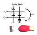
Simplified AND gate circuit using diodes.svg 257 × 272; 8 KB
-
Slicer circuit jp.svg 760 × 200; 36 KB
-
Three diodes.png 2,256 × 1,380; 80 KB
-
Transistor Clock.jpg 2,096 × 2,696; 898 KB
-
Two batteries, one with diode.png 1,128 × 1,040; 62 KB
-
USM zatizeny.png 371 × 159; 20 KB
-
Voltage multiplier with DC output.TIF 1,209 × 636; 55 KB
-
VoltageRegulator.png 518 × 287; 21 KB
-
Zasada działania transila.svg 218 × 173; 29 KB
-
ZavernySmer.jpg 162 × 134; 5 KB
-
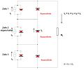
Zenerbarriere.png 524 × 287; 13 KB


