Category:Teaching illustrations of electronics
Jump to navigation
Jump to search
Subcategories
This category has the following 2 subcategories, out of 2 total.
C
V
Media in category "Teaching illustrations of electronics"
The following 200 files are in this category, out of 718 total.
(previous page) (next page)-
 0 to 4 TTL gates student.JPG 2,304 × 1,653; 269 KB
-
 2-e134z1234i1234s12.png 362 × 248; 3 KB
-
 2-spolar.svg 244 × 253; 21 KB
-
 741 input stab block 1000.jpg 1,000 × 614; 91 KB
-
 741 input stab detail 1000.jpg 1,000 × 1,277; 200 KB
-
 741 input stab tca 1000.jpg 1,000 × 685; 105 KB
-
 A compensated voltage summer with an output.jpg 654 × 586; 52 KB
-
 A computerized laboratory setup for demonstration.jpg 1,000 × 673; 289 KB
-
 A screenshot of a 'live' resistor summer.jpg 1,000 × 750; 36 KB
-
 A snapshot of a 'live' virtual ground.jpg 1,000 × 750; 52 KB
-
 Adapt-sch-es.png 285 × 174; 2 KB
-
 Adaptation d'impédance wv.png 430 × 421; 9 KB
-
 Adaptation d'impédance-wv-2.png 159 × 165; 5 KB
-
 AMM MG-Einfluss I.svg 540 × 290; 27 KB
-
 Ampe ke.gif 128 × 121; 1 KB
-
 AN PAQ-1 Laser Designator.jpg 795 × 521; 100 KB
-
Animación 3D de un panel eléctrico.ogv 13 s, 960 × 540; 8.18 MB
-
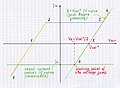
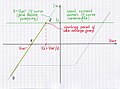
 Animated by IV curves V-to-I converter.png 1,366 × 626; 117 KB
-
 Anti load.jpg 826 × 576; 35 KB
-
 Antilog volt comp 1000.jpg 1,000 × 712; 114 KB
-
 Antilog volt comp graph 1000.jpg 1,000 × 714; 103 KB
-
 Antiparallelschaltung Dioden.svg 155 × 280; 2 KB
-
 APCh2.svg 180 × 250; 16 KB
-
 Attenuators Tee Pi L.png 3,151 × 976; 80 KB
-
 Basic circuit.PNG 1,516 × 967; 64 KB
-
 Basic electric circuit.svg 138 × 105; 13 KB
-
 Basic Set.jpg 1,104 × 1,094; 474 KB
-
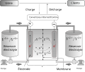 Batterie vanadium redox principe.svg 617 × 519; 91 KB
-
 Batteries parallel series.png 577 × 180; 4 KB
-
 Belasteter Spannungsteiler.svg 441 × 459; 11 KB
-
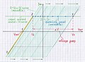
 Bipolar resistive summer - voltage diagram.jpg 3,921 × 2,743; 602 KB
-
 Bistable inic 10-1a 1000.jpg 1,000 × 736; 90 KB
-
 Bistable inic 10-1b 1000.jpg 1,000 × 744; 106 KB
-
 Bistable inic 10-2a 1000.jpg 1,000 × 743; 96 KB
-
 Bistable inic 10-2a.jpg 3,196 × 2,376; 1.05 MB
-
 Bistable inic 10-2b 1000.jpg 1,000 × 747; 106 KB
-
 Bistable inic 10-3a 1000.jpg 1,000 × 742; 91 KB
-
 Bistable inic 10-3b 1000.jpg 1,000 × 779; 113 KB
-
 Bistable inic 11a 1000.jpg 1,000 × 738; 96 KB
-
 Bistable inic 11b 1000.jpg 1,000 × 780; 113 KB
-
 Bistable inic 2b 1000.jpg 1,000 × 750; 115 KB
-
 Bistable inic 3b 1000.jpg 1,000 × 765; 115 KB
-
 Bistable inic 4b 1000.jpg 1,000 × 752; 108 KB
-
 Bistable inic 5-1a 1000.jpg 1,000 × 741; 91 KB
-
 Bistable inic 5-1b 1000.jpg 1,000 × 746; 107 KB
-
 Bistable inic 5-2a 1000.jpg 1,000 × 722; 102 KB
-
 Bistable inic 5-2b 1000.jpg 1,000 × 749; 108 KB
-
 Bistable inic 5-2b new 1000.jpg 1,000 × 746; 108 KB
-
 Bistable inic 5-2b new2 1000.jpg 3,048 × 2,284; 1.03 MB
-
 Bistable inic 5-3a 1000.jpg 1,000 × 740; 92 KB
-
 Bistable inic 5-3b 1000.jpg 1,000 × 747; 105 KB
-
 Bistable inic 5-3b new2 1000.jpg 1,000 × 747; 108 KB
-
 Bistable inic 6b 1000.jpg 1,000 × 748; 106 KB
-
 Bistable inic 6b new 1000.jpg 1,000 × 747; 106 KB
-
 Bistable inic 6b new2 1000.jpg 1,000 × 750; 106 KB
-
 Bistable inic 6b new3 1000.jpg 3,052 × 2,280; 976 KB
-
 Bistable inic 7a 1000.jpg 1,000 × 735; 98 KB
-
 Bistable inic 7b 1000.jpg 1,000 × 747; 107 KB
-
 Bistable inic 7b new 1000.jpg 1,000 × 745; 109 KB
-
 Bistable inic 7b new2 1000.jpg 1,000 × 744; 107 KB
-
 Bistable inic 8a 1000.jpg 1,000 × 740; 96 KB
-
 Bistable inic 8b new 1000.jpg 1,000 × 743; 103 KB
-
 Bistable inic 8b new1 1000.jpg 1,000 × 745; 103 KB
-
 Bistable inic 9a 1000.jpg 1,000 × 738; 99 KB
-
 Bistable inic 9b 1000.jpg 1,000 × 747; 106 KB
-
 Bjt current mirror full 1000.jpg 1,000 × 702; 66 KB
-
 Bjt current mirror in 1000.jpg 1,000 × 1,441; 90 KB
-
 Bjt current mirror in iv 450.jpg 450 × 324; 14 KB
-
 Bjt current mirror out 1000.jpg 1,000 × 1,425; 91 KB
-
 Bjt current mirror out iv 450.jpg 450 × 324; 14 KB
-
 Boost converter anim.gif 861 × 351; 348 KB
-
 Bootstrapped current source 65b 1000.jpg 1,000 × 731; 58 KB
-
 Bridge rectifier 1.png 406 × 163; 5 KB
-
 Bridge rectifier.png 406 × 162; 5 KB
-
 BRIDGERECTIFIERJAS.jpg 1,115 × 1,723; 81 KB
-
 Brücke.svg 496 × 301; 34 KB
-
 Build summer - STEP 2.jpg 653 × 586; 39 KB
-
 Build summer - STEP 3.jpg 653 × 585; 47 KB
-
 Build summer 1.jpg 651 × 586; 26 KB
-
-
 Cap dif volt comp 1000.jpg 1,000 × 713; 112 KB
-
 Cap dif volt comp graph 1000.jpg 1,000 × 713; 103 KB
-
 Cap int volt comp graph 1000.jpg 1,000 × 708; 105 KB
-
 Capacite.png 330 × 252; 13 KB
-
 Capacitor serial.svg 560 × 150; 7 KB
-
 Cascode-voltage-ladder.png 398 × 539; 1 KB
-
 Cdr.GIF 512 × 384; 3 KB
-
 Chung 1 1000.jpg 1,000 × 1,428; 190 KB
-
 Chung 2 1000.jpg 1,000 × 1,425; 195 KB
-
 Chung 3 1000.jpg 1,000 × 1,425; 198 KB
-
 Chung 4 1000.jpg 1,000 × 759; 142 KB
-
 Chung 5 1000.jpg 1,000 × 757; 134 KB
-
 Chung 6 1000.jpg 1,000 × 711; 118 KB
-
 Chung 7 1000.jpg 2,466 × 1,761; 803 KB
-
 Cic66.png 765 × 327; 16 KB
-
 Cic70.png 746 × 317; 15 KB
-
 Cic80.png 765 × 334; 15 KB
-
 Cicl100.png 1,272 × 489; 28 KB
-
 Cicl66.png 1,414 × 553; 40 KB
-
 Cicl70.png 1,266 × 497; 33 KB
-
 Cicl80.png 1,382 × 544; 44 KB
-
 Ciclo 100%.jpg 571 × 240; 89 KB
-
 Circuit condensateur.png 284 × 216; 2 KB
-
 Circuit diagram – pictorial and schematic.png 398 × 551; 27 KB
-
 Circuit dérivation Tensions.png 500 × 400; 5 KB
-
 Circuit serie.jpg 453 × 272; 12 KB
-
 Circuit série Tension.png 500 × 400; 5 KB
-
 Circuit with transformator.png 679 × 340; 17 KB
-
 Circuit1.jpg 174 × 290; 23 KB
-
 Circuit1new.jpg 174 × 290; 9 KB
-
 Circuit2.jpg 216 × 190; 10 KB
-
 Circuito 2B.png 851 × 476; 20 KB
-
 Circuito básico de polarización directa de LEDs.jpg 816 × 417; 32 KB
-
 Circuito básico de polarización directa de un led.jpg 339 × 420; 12 KB
-
 Circuito básico de polarización directa de varios ledes.jpg 437 × 465; 16 KB
-
 Circuito rectificador media onda OFF.png 146 × 97; 671 bytes
-
 CircuitoAmperimetro.png 368 × 404; 12 KB
-
 CircuitoRC.jpg 288 × 145; 5 KB
-
 Circuitosimple.jpg 561 × 285; 10 KB
-
 Circuits.png 498 × 212; 10 KB
-
 Circuits.svg 690 × 762; 58 KB
-
 CircuitWithShort.xcf 359 × 208; 57 KB
-
 Cirucito rectificador con filtro.png 304 × 184; 11 KB
-
 CirucitoVoltimetro.png 368 × 404; 12 KB
-
 Common-source amplifier graph STEP 2.1.png 1,111 × 467; 47 KB
-
 Common-source amplifier STEP 1.png 1,024 × 435; 5 KB
-
 Common-source amplifier STEP 2.1.png 1,024 × 592; 11 KB
-
 Communicating vessels as analogy.jpg 639 × 400; 25 KB
-
 Communicating vessels.jpg 639 × 400; 17 KB
-
 COmparatorHIGH.JPG 299 × 188; 21 KB
-
 COmparatorLow.JPG 312 × 191; 22 KB
-
 Compensated voltage summer.jpg 653 × 588; 50 KB
-
 Complementary circuit.PNG 261 × 146; 3 KB
-
 Conceptual inverting summer 0.jpg 686 × 526; 58 KB
-
 Conceptual inverting summer 1.jpg 680 × 466; 35 KB
-
 Condensateur decharge.png 242 × 135; 3 KB
-
 Condensateur.PNG 226 × 189; 3 KB
-
 Conventional circuit.svg 400 × 325; 7 KB
-
 Active rc integrator how to convert 450.jpg 450 × 650; 33 KB
-
 RC integrator 1000.jpg 1,000 × 710; 55 KB
-
 Relax versus LC 1000.jpg 1,000 × 638; 39 KB
-
 Sin phase6 1000.jpg 1,000 × 710; 26 KB
-
 Sinusoid 1000.jpg 1,000 × 716; 29 KB
-
 Steady quantity 1000.jpg 1,000 × 707; 19 KB
-
 Steady sources 1000.jpg 1,000 × 710; 36 KB
-
 Sun phases 1000.jpg 1,000 × 734; 29 KB
-
 Courant 2.svg 188 × 164; 18 KB
-
 Courant 3.svg 132 × 164; 13 KB
-
 Cours 03 image 01.png 792 × 685; 23 KB
-
 Cours 03 image 03.png 779 × 605; 19 KB
-
 Creating nic 1000.jpg 1,000 × 707; 73 KB
-
 Creating simplest neg rez 1000.jpg 1,000 × 709; 106 KB
-
 Creating simplest neg rez.jpg 2,504 × 1,832; 730 KB
-
 Creating simplest op-amp neg rez 1000.jpg 1,000 × 711; 110 KB
-
 CRECT5.png 1,446 × 1,063; 44 KB
-
 Cricuitosim.jpg 561 × 285; 8 KB
-
 Crystal detector.jpg 1,513 × 946; 103 KB
-
 Crystal Radio Circuit.png 300 × 200; 1 KB
-
 Current division example.PNG 775 × 535; 49 KB
-
 Current division example.svg 775 × 535; 21 KB
-
 Current Flow ml.svg 248 × 283; 7 KB
-
 Current Flow-bn.svg 211 × 274; 7 KB
-
 Current Flow-gu.svg 211 × 274; 6 KB
-
 Current Flow-hi.svg 211 × 274; 7 KB
-
 Current Flow-kn.svg 211 × 274; 5 KB
-
 Current Flow-pa.svg 211 × 274; 5 KB
-
 Current Flow-ru.svg 195 × 291; 986 bytes
-
 Current Flow-ta.svg 211 × 274; 5 KB
-
 Current Flow-te.svg 211 × 274; 5 KB
-
 Current Flow.svg 211 × 274; 15 KB
-
 Current mirror pushing2ib 1000.jpg 1,000 × 1,196; 145 KB
-
 Current mirror pushing2ib a 1000.jpg 1,000 × 1,196; 162 KB
-
 Current mirror sinking and sucking2ib 1 a 1000.jpg 1,000 × 1,201; 177 KB
-
 Current mirror sinking and sucking2ib a 1000.jpg 1,000 × 1,187; 161 KB
-
 Current mirror sinking and sucking2ib b 1000.jpg 1,000 × 1,187; 164 KB
-
 Current mirror sucking2ib 1000.jpg 1,000 × 1,196; 147 KB
-
 Current mirror sucking2ib a 1000.jpg 1,000 × 1,195; 164 KB
-
 Current mirror trans diode whiteboard 66b.jpg 480 × 640; 26 KB
-
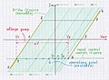
 Current-driven neg resistor graph 1000.jpg 1,000 × 716; 92 KB
-
 Current-driven neg resistor idea 1000.jpg 1,000 × 712; 96 KB
-
 Current-driven resistor graph 1000.jpg 1,000 × 716; 90 KB
-
 Dangle1.jpg 422 × 292; 17 KB
-
 Dangle2.jpg 304 × 254; 12 KB
-
 Dcdemo.png 492 × 309; 2 KB
-
 Dciswitch.png 498 × 327; 2 KB
-
 Diagramma vettoriale delle tensioni a circuito aperto.png 325 × 383; 8 KB
-
 Different voltages.png 213 × 240; 5 KB
-
 Diobicolor.png 454 × 125; 2 KB
-
 Diode AND logic idea 1000.JPG 1,000 × 961; 48 KB
-
 Diviseur de courant cc.svg 390 × 213; 4 KB
-
 Ecl current curves 1000.jpg 1,000 × 684; 104 KB
-
 ECL logical0 1000.jpg 1,000 × 690; 130 KB
-
 Ecl logical1 1000.jpg 1,000 × 693; 134 KB
-
 ECL logical1 1000.jpg 1,000 × 694; 133 KB
-
 Ecl structure 1000.jpg 1,000 × 711; 109 KB
-
 ECL structure 1000.jpg 1,000 × 714; 106 KB
-
 ECL transition 1000.jpg 1,000 × 691; 128 KB
-
 ECL voltage current picture 1000.jpeg 1,000 × 667; 121 KB
-
 Effet photoelectrique 001.jpg 575 × 538; 40 KB
-
 Ein-Zu-Dreiphasensystem.svg 570 × 400; 95 KB


