Category:Main earthing busbar
Jump to navigation
Jump to search
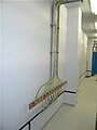
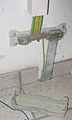
English: Busbar, which distributes ground pole to all metal parts in installation. All ground (Protection Earth) wires must be connected only to main ground busbar instead of neutral wire or pipes, cause main earthing busbar is designed to supply constant contact with earth and falling of neutral wire wouldn't cause lethal voltage on metal parts.
- Neutral wire might be connected to main earthing busbar only in TN-C-S system as auxilary wire.
Media in category "Main earthing busbar"
The following 20 files are in this category, out of 20 total.
-
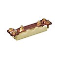 Barrette-de-terre.jpg 458 × 458; 13 KB
-
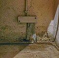
 Distribution board in Slovakia 08.jpg 4,000 × 3,000; 3.54 MB
-
 Dornbirn-modern main earthing busbar (copper)-01ASD - Kopie.jpg 4,624 × 3,468; 3.66 MB
-
 Dornbirn-old main earthing busbar (copper)-01ASD.jpg 4,624 × 1,802; 1.2 MB
-
 Equipotential bonding box.jpg 800 × 610; 128 KB
-
 Erder fuer Fundament.jpg 1,296 × 1,282; 1,004 KB
-
 Fundamenterder.jpg 590 × 742; 110 KB
-
 Intersystem Bonding Termination With Cover On.jpg 4,032 × 3,024; 1.32 MB
-
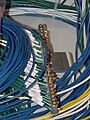
 IZ4AKS-BY1RX - Beijing - China - Nov. 09 (4083361754).jpg 3,072 × 2,304; 4.7 MB
-
 Listwa uziemiająca.jpg 4,000 × 3,000; 3.12 MB
-
 Main earthing busbar 215.jpg 960 × 1,280; 541 KB
-
 Main earthing busbar.JPG 7,300 × 5,480; 8.33 MB
-
 Main ground busbar.JPG 480 × 640; 42 KB
-
 Peamaanduslatt (ET).JPG 2,480 × 1,700; 359 KB
-
 Potentialausgleichsschiene unbeschaltet.jpg 491 × 319; 8 KB
-
 Potenzialausgleichsschiene.jpg 986 × 1,648; 161 KB
-
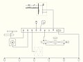 Technical diagram of the main earthing busbar in TN-C system.JPG 1,000 × 742; 65 KB
-
 Technical diagram of the main earthing busbar in TN-C-S system.jpg 1,080 × 760; 67 KB
-
 Technical diagram of the main earthing busbar in TN-S.JPG 1,000 × 742; 66 KB
-
 Technical diagram of the main earthing busbar in TT and IT systems.JPG 1,000 × 742; 64 KB


-01ASD_-_Kopie.jpg)


.jpg)


.JPG)


-01ASD.jpg)