Category:Vacuum tube circuits
Jump to navigation
Jump to search
Subcategories
This category has the following 5 subcategories, out of 5 total.
A
- April 1916 QST (20 F)
C
- Cathode follower (5 F)
O
- Octode circuits (1 F)
V
- Vacuum diode logic (1 F)
- Vacuum triode circuits (17 F)
Media in category "Vacuum tube circuits"
The following 112 files are in this category, out of 112 total.
-
 1915 Armstrong Tickler regen receiver.gif 327 × 313; 8 KB
-
 Additron Tube schematic.png 994 × 654; 134 KB
-
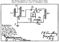
 Ammodstage.jpg 611 × 473; 24 KB
-
 April 1916 QST.djvu 2,550 × 3,300, 28 pages; 1.93 MB
-
 Armstrong circuit.png 679 × 488; 47 KB
-
 Audion.png 170 × 284; 5 KB
-
 Audion.svg 512 × 512; 8 KB
-
 AudionMitRück.GIF 725 × 496; 7 KB
-
 AudionOhneRK.PNG 720 × 455; 7 KB
-
 Beam Deflection Tube basic circuit.png 918 × 600; 5 KB
-
 Blocking Generator.png 250 × 370; 4 KB
-
 Blocking oscillator.svg 882 × 630; 15 KB
-
 Carcinotron.png 320 × 224; 1 KB
-
 Cascode-triode-full.png 462 × 419; 2 KB
-
 Circlotron basic schematic.png 426 × 372; 5 KB
-
 Clapp-oscillator tube.svg 517 × 376; 32 KB
-
 Colpitts Osz Patent Fig2.png 859 × 668; 13 KB
-
 Demodulator 01.gif 1,431 × 742; 16 KB
-
 Demodulator AM 01.gif 864 × 638; 8 KB
-
 Dke38.gif 640 × 480; 8 KB
-
 Duodiode.png 400 × 310; 4 KB
-

-
 EB1911 Telegraph - wireless receiver using oscillation valve.jpg 846 × 690; 56 KB
-
 EB1922 Telephone - Telephone repeater circuit.jpg 781 × 466; 64 KB
-
 Edison-richardson-effekt.gif 240 × 240; 5 KB
-
 Edisoneffect finnish labels.png 94 × 394; 891 bytes
-
 EdisonEffect-ru.svg 741 × 581; 2 KB
-
 Edisoneffect.es.png 115 × 332; 6 KB
-
 Edisoneffect.png 115 × 332; 661 bytes
-
 EdisonEffect.svg 194 × 581; 8 KB
-
 Edisoni efekti joonis.svg 194 × 581; 8 KB
-
 Effet Edison.png 115 × 332; 754 bytes
-
 Eintakt-Roehrenverstaerker.png 346 × 252; 5 KB
-
 EPC Blockschaltbild.jpeg 882 × 594; 146 KB
-
 Follower.JPG 320 × 256; 4 KB
-
 Freqdoublermade using triodes.jpg 326 × 420; 14 KB
-
 Freqtripliermade of triodes.jpg 368 × 415; 13 KB
-
 Gittervorspannung.svg 375 × 375; 13 KB
-
 Gloria-SW3-schaltung.jpg 622 × 416; 82 KB
-
 GMteller.png 680 × 326; 7 KB
-
 Goc9.png 575 × 338; 13 KB
-
 Goodmixer.jpg 400 × 461; 15 KB
-
 Hartley-US-Pat 1,356,7631.png 800 × 600; 77 KB
-
 Heegner Schaltung Patentschrift.png 421 × 206; 5 KB
-
 Heptode Pentagrid.png 300 × 492; 12 KB
-
 Hook-up of 8TY's station from the April 1916 QST.png 1,516 × 892; 29 KB
-
 HV Vib.jpg 1,055 × 557; 110 KB
-
 Jan 1916 QST Oscillating Audion.png 1,249 × 652; 21 KB
-
 Klystron 3.png 1,646 × 684; 20 KB
-
 Klystron back.png 1,128 × 851; 18 KB
-
 Klystron.png 1,646 × 684; 19 KB
-
 Likriktare tube.png 320 × 256; 3 KB
-
 Magnetron sch.jpg 379 × 234; 12 KB
-
 Meissner Patent.png 428 × 456; 9 KB
-
 Mixer oktode.png 224 × 325; 1 KB
-
 Mixer tetrode.PNG 254 × 356; 1 KB
-
 Mullard 3-3 rus.png 970 × 640; 35 KB
-
 Oscillator Colpitts 1920 svg.png 420 × 310; 10 KB
-
 P-120-row-220.jpg 1,153 × 600; 160 KB
-
 Pol tube grille.png 281 × 238; 1,007 bytes
-
 Pol tube RK.png 581 × 261; 2 KB
-
 Pol tube source de tesion.png 281 × 238; 950 bytes
-
 ProjectTinkertoy 046.jpg 4,311 × 5,411; 11.58 MB
-
 ProjectTinkertoy 047.jpg 3,094 × 4,268; 7.16 MB
-
 ProjectTinkertoy 050.jpg 5,633 × 4,524; 22.84 MB
-
 ProjectTinkertoy 065.jpg 3,199 × 5,711; 8.8 MB
-
 ProjectTinkertoy 066.jpg 2,944 × 5,350; 6.77 MB
-
 ProjectTinkertoy 067.jpg 3,229 × 5,591; 8.52 MB
-
 ProjectTinkertoy 068.jpg 3,169 × 5,681; 7.23 MB
-
 ProjectTinkertoy 069.jpg 5,708 × 3,772; 19.64 MB
-
 ProjectTinkertoy 070.jpg 3,590 × 5,711; 19.43 MB
-
 QST (1915) (14735564576).jpg 2,318 × 3,300; 632 KB
-
 Radio Hat Circuit.jpg 618 × 182; 59 KB
-
 Radio-mixer.png 320 × 256; 4 KB
-
 Radio-oscillator3.png 320 × 256; 4 KB
-
 Ring modulator 01.gif 289 × 177; 2 KB
-
 RoehrenverstaerkerGittervorspannung.jpg 1,752 × 1,748; 256 KB
-
 Schaltbild Franck Hertz Versuch.png 396 × 208; 3 KB
-
 Schaltskizze Elektromechanischer Zerhacker.svg 505 × 285; 18 KB
-
 Schema match tube.jpg 800 × 511; 82 KB
-
 Screenmodulator.jpg 644 × 390; 23 KB
-
 Seiler oscillator triode2.png 310 × 190; 4 KB
-
 Seriesmod.jpg 579 × 579; 35 KB
-
 Seriesmod.png 579 × 579; 4 KB
-
 Sumovy generator s vakuovou diodou.png 1,112 × 789; 57 KB
-
 Tri-Tet Oscillator Schematic.PNG 776 × 703; 16 KB
-
 Tube power opt dir.png 320 × 256; 4 KB
-
 Tube power opt drive.png 320 × 256; 4 KB
-
 Tube power opt pre.png 320 × 256; 4 KB
-
 Tube power opt.png 320 × 256; 4 KB
-
 Tube power opt2.png 320 × 256; 4 KB
-
 Tube power rect.png 320 × 256; 4 KB
-
 Tube power rect2.png 320 × 256; 4 KB
-
 Tube push pull poweramplifier.PNG 440 × 330; 1 KB
-
 Tube riaa.png 350 × 256; 5 KB
-
 TWT M.png 1,596 × 532; 19 KB
-
 TWT.png 1,646 × 665; 25 KB
-
 Vackar oscillator triode.png 300 × 150; 3 KB
-
 VacRect2E.png 301 × 306; 14 KB
-
 VacRect2E.svg 329 × 383; 15 KB
-
 Vacuum tube audion.png 650 × 406; 2 KB
-
 Vacuum Tube Auidion hu.svg 908 × 436; 46 KB
-
 Vacuum tube plate detector schematic diagram drawn by Eric LaGess Jan 2018.png 1,775 × 1,117; 38 KB
-
 Van der pol triode.svg 800 × 600; 24 KB
-
 VIBRATOR VPM.JPG 1,632 × 1,224; 314 KB
-
 Werking reflexklystron.png 1,401 × 759; 10 KB
-
 Western Electric 86 300B output stage.png 847 × 742; 49 KB
-
 Western Electric 91 300B output stage.png 607 × 722; 49 KB
-
 Western Electric 92 300B output stage.png 956 × 943; 69 KB
-
 Wien bridge oscillator with triodas.svg 1,052 × 744; 82 KB
-
 КВН-49-4.jpg 5,052 × 3,820; 2.88 MB
-
 Ультралинейный режим.png 1,175 × 390; 21 KB


_(14735564576).jpg)


