Category:Resistor circuits
Jump to navigation
Jump to search
Subcategories
This category has the following 2 subcategories, out of 2 total.
A
- Resistive circuit analysis (27 F)
T
Pages in category "Resistor circuits"
This category contains only the following page.
Media in category "Resistor circuits"
The following 200 files are in this category, out of 276 total.
(previous page) (next page)-
 1 en série puis 2 résistances en parallèle puis 1 en série.svg 736 × 133; 14 KB
-
 1 en série puis 4 résistances en parallèle puis 1 en série.svg 736 × 291; 21 KB
-
 1k resistor on.JPG 640 × 480; 62 KB
-
 2 en série puis 2 fois 4 série en parallèle puis 2 en série.svg 963 × 438; 41 KB
-
 2 resistors in parallel.png 206 × 147; 8 KB
-
 2 resistors in series.png 170 × 128; 460 bytes
-
 2 résistances en parallèle puis 1 en série.svg 536 × 133; 11 KB
-
 2 résistances en parallèle.svg 331 × 133; 8 KB
-
 2 résistances en série.svg 450 × 63; 7 KB
-
 3wire resistive loads balanced.svg 204 × 250; 81 KB
-
 3wire resistive loads.PNG 350 × 260; 6 KB
-
 3wire resistive loads.svg 993 × 639; 33 KB
-
 4T SRAM Cell.png 910 × 567; 20 KB
-
 Ac-resistor-circuit.svg 151 × 113; 2 KB
-
 Acidemo.png 523 × 303; 1 KB
-
 AsociacionesMixtas.png 340 × 436; 16 KB
-
 AsociacionEstrellaTriangulo.png 492 × 196; 12 KB
-
 AsociacionSerieParalelo.png 433 × 372; 13 KB
-
 AsociacioSerieParaleloZ.png 424 × 356; 10 KB
-
 Associação de resistencia.png 299 × 110; 3 KB
-
 Associação de resistencia.svg 512 × 188; 2 KB
-
 Attenuator, general L-section.svg 442 × 384; 10 KB
-
 Attenuator, T-section from L-sections.svg 582 × 384; 29 KB
-
 Attenuator, T-section.svg 582 × 384; 20 KB
-
 Basic resistance diagram.jpg 1,002 × 477; 304 KB
-
 Basic series circuit.jpg 481 × 301; 11 KB
-
 Capacitor resistor series.svg 524 × 372; 9 KB
-
 Carey Foster bridge.svg 500 × 225; 33 KB
-
 Charge on Photosensitive Capacitor.png 5,175 × 2,308; 180 KB
-
 Circuit diagram 1.jpg 253 × 161; 7 KB
-
 Circuit diagram 2.jpg 269 × 233; 11 KB
-
 Circuit diagram 3.jpg 255 × 192; 8 KB
-
 Circuit diagram 4b.jpg 260 × 189; 8 KB
-
 Circuit diagram 6b.jpg 286 × 212; 10 KB
-
 Circuit diagram 9.jpg 433 × 386; 15 KB
-
 Circuit diagram of logarithmic ladder DA converter, Mar 2012.png 877 × 200; 3 KB
-
 Circuit Scheme.png 1,210 × 659; 66 KB
-
 Circuito - 2.png 316 × 192; 3 KB
-
 Circuito Elettrico 2.svg 319 × 213; 23 KB
-
 Circuito elettricoDocument.svg 340 × 281; 41 KB
-
 Circuito equivalente.png 202 × 70; 1 KB
-
 Circuito1.png 382 × 210; 5 KB
-
 CircuitoResistivo.png 371 × 236; 7 KB
-
 CircuitosDivisores.png 446 × 330; 10 KB
-
 Collector to base bias.svg 476 × 504; 6 KB
-
 ColpittsOscillator-JFET-SR.svg 574 × 362; 7 KB
-
 Combo1.png 493 × 354; 11 KB
-
 Combo2.png 447 × 366; 11 KB
-
 Combo3.png 439 × 336; 13 KB
-
 Combo4.png 448 × 340; 13 KB
-
 Conductimetrie005.png 290 × 158; 2 KB
-
 Courant 1.svg 128 × 164; 13 KB
-
 CPT-Logic-AND-Switch.svg 664 × 514; 9 KB
-
 Current division.PNG 788 × 277; 42 KB
-
 Current follower resistor load.PNG 543 × 688; 49 KB
-
 Current follower resistor load.svg 160 × 239; 3 KB
-
 DC circuit 3 resistors 1 voltage source.svg 205 × 156; 32 KB
-
 Delic.png 249 × 353; 7 KB
-
 DielnikNapiecia.svg 744 × 524; 7 KB
-
 DielnikPradu.svg 500 × 500; 9 KB
-
 DIODO IDEAl polarizacion directa.JPG 320 × 210; 12 KB
-
 Diodo ideal polarizado en directa.gif 283 × 211; 2 KB
-
 Diviseur courant 2R.png 430 × 500; 93 KB
-
 Diviseur courant 3R.png 500 × 415; 85 KB
-
 Diviseur de tension.png 222 × 238; 4 KB
-
 Diviseur tension 3R.png 500 × 168; 148 KB
-
 Diviseur tension chargé.png 500 × 198; 73 KB
-
 Diviseur tension.png 500 × 228; 57 KB
-
 Divisor corriente resistivo.gif 465 × 222; 6 KB
-
 Dual Z 5.PNG 538 × 119; 2 KB
-
 Dual Z 6.PNG 331 × 232; 3 KB
-
 EBurkisdia1TIS.png 328 × 205; 5 KB
-
 Elcep2.png 693 × 365; 14 KB
-
 Electronic circuit to illustrate the interval propagation.gif 774 × 721; 7 KB
-
 Electronics R.PNG 89 × 84; 578 bytes
-
 Electronics R.svg 89 × 85; 833 bytes
-
 Electronics R2S.PNG 89 × 85; 697 bytes
-
 Electronics R2S.svg 89 × 85; 889 bytes
-
 Electronics R3S.PNG 89 × 85; 761 bytes
-
 Electronics R3S.svg 89 × 85; 953 bytes
-
 Ellenallas parhuzamos.svg 425 × 283; 9 KB
-
 Ellenallas soros.svg 425 × 213; 8 KB
-
 Emira.jpg 867 × 520; 11 KB
-
 Esb z1 z0.JPG 448 × 376; 14 KB
-
 Estrella-triangle.svg 509 × 813; 19 KB
-
 Example-resistors-2.JPG 465 × 402; 24 KB
-
 Example18a.png 508 × 340; 24 KB
-
 Example25a.png 336 × 270; 34 KB
-
 Example25b.png 334 × 238; 17 KB
-
 Five-resistor-network-vert.svg 182 × 185; 13 KB
-
 Five-resistor-network.svg 179 × 159; 13 KB
-
 Fixed bias with emitter resistor.PNG 407 × 497; 15 KB
-
 Fixed bias with emitter resistor.svg 504 × 588; 6 KB
-
 Fixed bias.PNG 426 × 498; 15 KB
-
 Fixed bias.svg 392 × 504; 5 KB
-
 Fonction transfert résistance.svg 1,259 × 1,259; 9 KB
-
 Gerador receptor.png 411 × 123; 6 KB
-
 I-inverted resistor - fixed gain amp implementation.JPG 3,064 × 2,016; 306 KB
-
 I-inverted resistor - source implementation.JPG 3,080 × 2,004; 247 KB
-
 I-inverted resistor.JPG 2,708 × 1,532; 167 KB
-
 I-to-v building 1000.jpg 1,000 × 706; 51 KB
-
 I-to-v trans switch 1000.jpg 1,000 × 707; 57 KB
-
 Image du théorème de Millman en potentiel.svg 325 × 177; 21 KB
-
 Interpoláló szelence-1.jpg 1,052 × 602; 39 KB
-
 IS THE WIRE A FOLLOWER1.PNG 750 × 294; 3 KB
-
 Istochnikeds snagruzkoj.png 384 × 526; 14 KB
-
 JerkCircuit01.png 922 × 571; 26 KB
-
 Kaynak.JPG 502 × 122; 7 KB
-
 Kelvin-Varley Spannungsteiler.svg 850 × 785; 69 KB
-
 Kirchhoff Rule.svg 257 × 124; 23 KB
-
 Kirchhoff-example-circuit-loops.svg 311 × 185; 17 KB
-
 KirchhoffLaws simple 1.svg 225 × 145; 56 KB
-
 Ladungsleitung 10.10.2009.pdf 1,160 × 737; 4 KB
-
 Light-dependent resistor equivalent.svg 404 × 455; 16 KB
-
 Linear inic 0b 1000.jpg 1,000 × 1,393; 203 KB
-
 Loi des mailles simplifiée.png 500 × 142; 66 KB
-
 Loi des mailles.png 500 × 367; 85 KB
-
 Messbereichserweiterung für Spannung U.png 197 × 125; 792 bytes
-
 Messbereichserweiterung für Ströme I.png 232 × 149; 788 bytes
-
 Mnak.jpg 368 × 251; 14 KB
-
 Multimeter resistor bank (6952361918).jpg 5,202 × 3,465; 2.44 MB
-
 NajprostszyObwod.svg 372 × 262; 13 KB
-
 Namur-Geber.jpg 343 × 158; 10 KB
-
 Neg imp volt compensation 1 1000.jpg 1,000 × 707; 104 KB
-
 NIC can act either as VNIC or INIC.JPG 2,553 × 1,464; 159 KB
-
 Ohms law current source (white background).svg 512 × 512; 784 bytes
-
 Ohms law voltage source (white background).svg 285 × 209; 7 KB
-
 Ohmscher-Spannungsteiler-Allgemein.svg 200 × 475; 23 KB
-
 Pad napona.jpg 224 × 609; 51 KB
-
 Pad napona2.jpg 217 × 331; 25 KB
-
 Para hallar el equivalente de Thevenin o de Norton de un circuito lineal.jpg 1,689 × 1,003; 164 KB
-
 ParalelniZapojeni.svg 178 × 156; 7 KB
-
 Paralelo de seriaj rezistiloj.png 600 × 253; 334 bytes
-
 Resistencias em paralelo.png 379 × 218; 6 KB
-
 Parallel circuit current.png 283 × 189; 5 KB
-
 Parallel resistances in disguise.gif 320 × 176; 348 KB
-
 Parallel resistors.svg 140 × 171; 11 KB
-
 Parallel Resistors.svg 241 × 120; 19 KB
-
 Parallel-connected resistor idea 1000.jpg 1,000 × 709; 98 KB
-
 ParallelR.png 293 × 136; 794 bytes
-
 Parallelschaltung Widerstände.svg 155 × 124; 35 KB
-
 Parallelschaltung.png 673 × 246; 4 KB
-
 ParalseriesR.png 136 × 79; 542 bytes
-
 Partitore di tensione con alimentatore.svg 218 × 162; 16 KB
-
 Partitori-cascata-buffer.png 366 × 245; 8 KB
-
 Partitori-cascata.png 258 × 243; 5 KB
-
 Passive i-to-v converter 1000.jpg 1,000 × 688; 58 KB
-
 Pi pad variaions.png 3,301 × 1,651; 49 KB
-
 Pi pad variations.png 3,301 × 1,651; 59 KB
-
 Pi-Schaltung.GIF 495 × 219; 3 KB
-
 Pi-Schaltung.svg 590 × 151; 27 KB
-
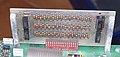 Plug-in Resistor Matrix board.jpg 2,334 × 1,108; 416 KB
-
 Ponte di diodi.svg 750 × 400; 38 KB
-
 Prechodovy jev RC.svg 208 × 151; 20 KB
-
 Prechodovy jev RL obvodu.svg 208 × 141; 19 KB
-
 Prechodovy jev RL.svg 208 × 141; 19 KB
-
 Prechodovy jev RLC.svg 208 × 151; 21 KB
-
 Qpole fr att L.svg 197 × 113; 14 KB
-
 Qpole fr att Lvar.svg 197 × 113; 14 KB
-
 Qpole fr att pi.svg 197 × 113; 16 KB
-
 Qpole fr att T.svg 197 × 113; 16 KB
-
 R bajo valor.jpg 564 × 222; 20 KB
-
 Razvetvelcep.png 693 × 371; 15 KB
-
 RC Divider.svg 172 × 161; 9 KB
-
 Real-Sch-Rezistoru.png 216 × 99; 466 bytes
-
 Rec2.jpg 387 × 148; 5 KB
-
 Reci1.jpg 391 × 138; 6 KB
-
 Reci3.jpg 381 × 138; 5 KB
-
 Recursion Rezisters 01.jpg 1,455 × 650; 52 KB
-
 Recursion Rezisters 02.jpg 1,930 × 238; 37 KB
-
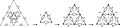 Recursion Rezisters 03.jpg 2,570 × 570; 306 KB
-
 Reihenschaltung Widerstände.svg 147 × 157; 16 KB
-
 Resistance in infinite grid.jpg 1,000 × 819; 120 KB
-
 Resistencias en serie.JPG 720 × 540; 24 KB
-
 Resistencias paralelo.JPG 451 × 203; 9 KB
-
 Resistenza di linea.svg 470 × 230; 29 KB
-
 Resistenze in parallelo.png 574 × 264; 4 KB
-
 Resistenze in serie.png 716 × 471; 4 KB
-
 Resistor circuit1.svg 502 × 340; 35 KB
-
 Resistor circuit2.svg 427 × 305; 45 KB
-
 Resistor desenho.jpg 3,552 × 1,906; 2.93 MB
-
 Resistor example.svg 118 × 70; 10 KB
-
 Resistor-example-1.JPG 394 × 335; 15 KB
-
 Resistors in Parallel.svg 300 × 120; 19 KB
-
 Resistors in parallel.svg 301 × 177; 49 KB
-
 Resistors in Series and Parallel.svg 250 × 88; 9 KB
-
 Resistors in series and parallel.svg 195 × 283; 45 KB
-
 Resistors in Series-modified.svg 335 × 50; 9 KB
-
 Resistors in Series.svg 375 × 125; 13 KB
-
 Resistors in series.svg 390 × 106; 44 KB
-
 Resistorscombo eu.svg 250 × 300; 8 KB
-
 Resistorscombo.png 125 × 177; 585 bytes
-
 Resistorsparallel eu.svg 227 × 150; 9 KB
-
 Resistorsparallel.png 189 × 91; 494 bytes
-
 Resistorsparallel.svg 227 × 150; 7 KB
-
 Resistorsseries eu.svg 227 × 50; 7 KB
-
 Resistorsseries.png 225 × 41; 503 bytes
-
 Resistorsseries.svg 227 × 50; 5 KB
-
 RPararell.svg 354 × 142; 20 KB
-
 Schaltung m-o Stromzweig.svg 230 × 270; 61 KB


.jpg)


.svg)
.svg)


