Category:Printed circuit board layout
Jump to navigation
Jump to search
Svenska: Komponentplacering på kretskort; kretskortslayout.
Subcategories
This category has the following 3 subcategories, out of 3 total.
T
- Teardrop (electronics) (13 F)
- Thermal reliefs (5 F)
V
- Via (electronics) (19 F)
Media in category "Printed circuit board layout"
The following 79 files are in this category, out of 79 total.
-
 Blantomat pcb ver 4 bw.jpg 451 × 310; 44 KB
-
 Board.png 892 × 448; 26 KB
-
 Circuit Design.jpg 2,576 × 2,155; 488 KB
-
 Ciruit.png 593 × 485; 11 KB
-
 CMOS LNA.jpg 376 × 337; 21 KB
-
 CR99001 CR99002 14 x 14 LS.jpg 264 × 227; 27 KB
-
 CR99003 22 x 32 LS.jpg 455 × 423; 49 KB
-
 CR99004 18 x 32 LS.jpg 470 × 488; 60 KB
-
 CR99005 22 x 30 LS.jpg 207 × 277; 21 KB
-
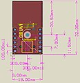
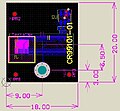 CR99101 18 x 20 HS.jpg 407 × 377; 63 KB
-
 CR99102 22 x 57.5 HS.jpg 202 × 395; 25 KB
-
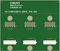 CR99210 triple maximum size carrier board.jpg 470 × 400; 53 KB
-
 Crystal Clear app hardware.png 128 × 128; 6 KB
-
 Crystal Clear app hardware.svg 128 × 128; 8 KB
-
 Current vs Width vs Temp (1oz ext).PNG 829 × 506; 38 KB
-
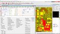
 DesignSpark PCB screenshot.png 1,920 × 1,227; 182 KB
-
 DSPCB Pro 9.0 screenshot.png 1,366 × 768; 165 KB
-
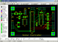
 Eagle pcb.png 800 × 574; 38 KB
-
 FreePCB screenshot.png 818 × 596; 21 KB
-
 GEDA screenshot2007 footprint crop.png 314 × 294; 10 KB
-
 GEDA screenshot2007.png 957 × 723; 77 KB
-
 Gerber-layers-example.png 232 × 1,000; 157 KB
-
 Gerber-Leiterplatten-Lagen.png 232 × 1,000; 172 KB
-
 Intel-pcb.png 1,210 × 822; 306 KB
-
 Interdigital Filter.jpg 1,104 × 1,795; 392 KB
-
 Kicad Pcbnew screenshot.jpg 923 × 656; 183 KB
-
 Kicad Pcbnew screenshot.PNG 923 × 655; 955 KB
-
 LCD 20x4 breadboard.svg 273 × 167; 222 KB
-
 LCD 20x4 pcb.svg 273 × 167; 19 KB
-
 LCD 20x4 schematic.svg 159 × 222; 16 KB
-
 Leiterbahnen IMGP2839 smial wp.jpg 7,360 × 4,912; 27.1 MB
-
 Lp3b.png 718 × 274; 40 KB
-
 Lpdkl.png 718 × 404; 33 KB
-
 M31 ofv final.jpg 942 × 1,299; 349 KB
-
 MakePCB-step0.jpg 450 × 436; 92 KB
-
 MakePCB-step1.jpg 450 × 243; 45 KB
-
 MakePCB-step2.jpg 429 × 264; 47 KB
-
 MakePCB-step4.jpg 429 × 264; 46 KB
-
 Manual ISP mm - dixon.png 4,640 × 2,610; 15.65 MB
-
 Manually trace extension mm - dixon.png 4,640 × 2,610; 12.49 MB
-
 Microstrip Directional Coupler.jpg 1,093 × 1,356; 338 KB
-
 Microstrip Sawtooth Directional Coupler.jpg 806 × 615; 114 KB
-
 Mini DIY circuit.svg 400 × 400; 15 KB
-

-

-
 Navrh plosny spoj soucastky.png 906 × 487; 28 KB
-
 Navrh plosny spoj vyroba.png 906 × 487; 7 KB
-
 ODB++ Design file extension logo.png 500 × 250; 8 KB
-
 PCB copper pour hatch filled.png 960 × 663; 130 KB
-
 PCB copper pour thermal pads.png 960 × 663; 58 KB
-
 PCB Cut Through Image.jpg 1,134 × 808; 485 KB
-
 PCB design and realisation smt and through hole.png 3,000 × 1,600; 2.74 MB
-
 PCB Design logo.png 169 × 108; 59 KB
-
 Pcb dlharmon screenshot.png 1,280 × 1,001; 218 KB
-
 Pcb eda.png 800 × 559; 134 KB
-
 PCB in a solution of ammonium sulphate.JPG 3,072 × 2,304; 2.41 MB
-
 PCB screenshot wiki.png 1,116 × 783; 150 KB
-
 PCB Sparkgap.jpg 663 × 486; 38 KB
-
 Pcblayout.png 718 × 404; 34 KB
-
 Pcbnew 3d viewer.png 516 × 392; 27 KB
-

-
 Rapid-pcb.jpg 255 × 185; 25 KB
-
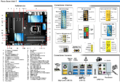
 Raspberrypi pcb overview Pinout v01.svg 524 × 372; 196 KB
-
 Rattennest.png 718 × 404; 46 KB
-
 Replacement of 4066 switch with optorelays layout.png 644 × 737; 82 KB
-
 SBC HD64180 Layout Part Side.jpg 3,899 × 2,506; 2.35 MB
-
 SBC HD64180 Layout Soldering Side.jpg 3,918 × 2,496; 2.28 MB
-
 SimpleTesla SSTC.jpg 3,504 × 2,336; 2.55 MB
-
 SimpleTesla ST3.jpg 3,325 × 2,092; 845 KB
-
 Topor approximation arcs.png 272 × 238; 39 KB
-
 Topor approximation lines.png 272 × 238; 28 KB
-
 Topor bga.gif 869 × 706; 59 KB
-
 Topor singlelayer.png 192 × 190; 34 KB
-
 Topor teardrops.gif 599 × 565; 55 KB
-
 Triple maximum size carrier board 67.72 x 57.5.jpg 470 × 401; 52 KB
-
 TryVLSI.jpg 367 × 459; 104 KB
-
 Wheeler Incremental Inductance Rule.png 5,550 × 3,600; 129 KB
-
 Zero-ohm link usecase.svg 404 × 285; 2 KB
-
 Автоматическое увеличение зазоров в TopoR.tif 926 × 810; 165 KB


.PNG)


.jpg)
.png)


