Category:Electrical power conversion diagrams
Jump to navigation
Jump to search
Subcategories
This category has the following 5 subcategories, out of 5 total.
C
- Charge pump circuits (17 F)
V
- Voltage doubler (28 F)
- Voltage regulator circuits (68 F)
Media in category "Electrical power conversion diagrams"
The following 149 files are in this category, out of 149 total.
-
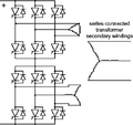
12-pulse inverter cjc.png 531 × 499; 11 KB
-
12-pulse inverter cjc.svg 512 × 481; 11 KB
-
3 phase rectification 2-ru.svg 737 × 1,052; 41 KB
-
3 phase rectification 2.svg 624 × 943; 120 KB
-
300px-Synch buck.PNG 300 × 143; 6 KB
-
4-switch Buck-Boost converter.svg 379 × 138; 37 KB
-
Active and passive sign convention.png 840 × 500; 7 KB
-
Active sign convention new.png 420 × 480; 4 KB
-
Active sign convention.svg 376 × 382; 13 KB
-
ACtoDCpowersupply.png 1,159 × 385; 46 KB
-
Allgemeine Polygonschaltung.svg 248 × 266; 23 KB
-
Allgemeine Sternschaltung.svg 248 × 266; 19 KB
-
Ansteuerlogik H-Bruecke.svg 550 × 500; 29 KB
-
B2c-gleichrichter-lückend.svg 450 × 300; 14 KB
-
B2c-gleichrichter-ohmsch.svg 450 × 300; 13 KB
-
B2Cschaltung.JPG 268 × 258; 8 KB
-
B2Cschaltung.svg 275 × 300; 16 KB
-
Basics of the 4-switch buck-boost converter-1.svg 722 × 1,375; 40 KB
-
Blokove schema zpetnovazebniho stabilizatoru.png 1,281 × 813; 89 KB
-
Boost conventions.svg 1,052 × 390; 87 KB
-
Boost convertor.svg 737 × 287; 2 KB
-
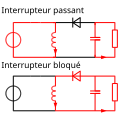
Boost operating fr.svg 744 × 750; 110 KB
-
Boost operating.svg 709 × 744; 41 KB
-
Buck conventions sr.svg 1,052 × 500; 84 KB
-
Buck conventions.svg 1,052 × 500; 84 KB
-
Buck Converter.jpg 370 × 178; 5 KB
-
BUCK converter.PNG 504 × 198; 6 KB
-
Buck operating fr.svg 1,052 × 744; 139 KB
-
Buck operating.svg 1,024 × 768; 41 KB
-
Buckboost conventions.svg 737 × 287; 2 KB
-
Buckboost operating fr.svg 744 × 744; 108 KB
-
Buckboost operating.svg 744 × 744; 149 KB
-
Circuito rectificador onda completa OFF.png 215 × 136; 3 KB
-
Circuito rectificador onda completa ON.png 215 × 136; 1 KB
-
Circuito rectificador onda completa.png 215 × 136; 3 KB
-
Commutation cell in converters.svg 625 × 1,052; 325 KB
-
Commutation cell practical theroretical.svg 1,052 × 744; 240 KB
-
Conversor Boost.png 640 × 320; 6 KB
-
CRMORL.jpg 440 × 212; 10 KB
-
Cuk conventions.svg 1,052 × 425; 136 KB
-
Cuk operating.svg 567 × 425; 158 KB
-
Cuk operating2.svg 1,052 × 461; 233 KB
-
Curva transferencia rectificador onda completa.png 211 × 137; 2 KB
-
Dcdc2qS1a.svg 300 × 180; 26 KB
-
Dcdc2qS1b.svg 300 × 180; 26 KB
-
Dcdc2qS2a.png 441 × 199; 8 KB
-
Dcdc2qS2b.png 441 × 199; 8 KB
-
Delon Schaltung Vierfach.svg 560 × 290; 48 KB
-
Delon Schaltung.svg 420 × 290; 34 KB
-
Delonschaltung ani.gif 475 × 240; 23 KB
-
Diagram Line-Commutated Converter LCC.png 1,628 × 598; 54 KB
-
Diagram Self-Commutated Voltage Source Converter VSC.png 1,463 × 464; 40 KB
-
Dubbelzijdige gelijkrichting met bruggelijkrichter.png 1,530 × 240; 29 KB
-
Dubbelzijdige gelijkrichting transformator.png 1,520 × 340; 32 KB
-
Durchflusswandler.png 470 × 491; 22 KB
-
Eintaktdurchflusswandler grundprinzip.svg 1,000 × 1,200; 43 KB
-
Eintaktdurchflusswandler.svg 1,200 × 450; 26 KB
-
Electric load animation 2.gif 270 × 331; 22 KB
-
Electric load animation.gif 270 × 331; 41 KB
-
Electric power source animation 2.gif 285 × 331; 30 KB
-
Electric power source animation.gif 285 × 331; 30 KB
-
Electrical diagram of Millbury substation, 1913.jpg 775 × 724; 104 KB
-
Enkelzijdige eenfase gelijkrichting.png 1,540 × 260; 24 KB
-
Fly-back converter.svg 301 × 178; 36 KB
-
Flyback conventions french.svg 482 × 238; 44 KB
-
Flyback conventions.svg 1,052 × 625; 135 KB
-
Flyback operating fr.svg 744 × 1,052; 167 KB
-
Flyback operating.svg 744 × 1,052; 135 KB
-
Flyback w snubber.svg 600 × 270; 89 KB
-
Flyback with primary leakage inductance french.svg 482 × 296; 45 KB
-
Forward-dwutranzystorowy.pdf 1,089 × 535; 23 KB
-
Full-wave stacked Villard cascade.svg 767 × 427; 47 KB
-
Full-wave Villard cascade.svg 733 × 321; 39 KB
-
Full-wave voltage doubler.svg 492 × 274; 27 KB
-
Fullwave.rectifier.en.png 769 × 208; 16 KB
-
Fullwave.rectifier.en.svg 760 × 170; 12 KB
-
Gratz.rectifier.en.png 769 × 171; 17 KB
-
Gratz.rectifier.en.svg 765 × 120; 10 KB
-
Greinacher circuit.png 1,295 × 445; 59 KB
-
Greinacher circuit.svg 509 × 181; 20 KB
-
Greinacher Schaltung.svg 440 × 160; 33 KB
-
Greinacherschaltung Funktion.PNG 555 × 114; 2 KB
-
H5 bridge.svg 700 × 300; 36 KB
-
Halfwave rectifier negative en.png 835 × 192; 14 KB
-
Halfwave rectifier two way en.png 844 × 275; 21 KB
-
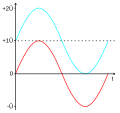
Halfwave-rectifier-graph.svg 461 × 336; 10 KB
-
Halfwave.rectifier.en.png 769 × 171; 14 KB
-
Halfwave.rectifier.en.svg 770 × 130; 9 KB
-
Hochspannungskaskade Funktion.PNG 642 × 246; 5 KB
-
Hochspannungskaskade.PNG 231 × 282; 831 bytes
-
Impulse power supply schematics.svg 744 × 354; 60 KB
-
Leistungssteller.svg 550 × 250; 10 KB
-
Mittelpunktgleichrichter.jpg 1,123 × 794; 73 KB
-
Multiphase buck.PNG 358 × 339; 7 KB
-
Passive sign convention new.png 420 × 480; 4 KB
-
Passive sign convention.svg 388 × 377; 15 KB
-
Positive Voltage Clamping V2.svg 355 × 270; 15 KB
-
Positive Voltage Clamping.svg 355 × 270; 18 KB
-
Power Supply 100W.jpg 885 × 675; 82 KB
-
Puente de diodos.png 238 × 199; 2 KB
-
Pulswechselrichter schaltung.PNG 815 × 407; 19 KB
-
Push-pull converter schematic.svg 550 × 240; 50 KB
-
Push-Pull converter.svg 430 × 360; 31 KB
-
Rect Trifasico contr.jpg 1,139 × 652; 83 KB
-
Rect Trifasico doce.jpg 526 × 770; 67 KB
-
S1 closed.jpg 684 × 224; 34 KB
-
S1 open.jpg 684 × 223; 35 KB
-
Schematic wiring diagram of power adapter.JPG 1,655 × 570; 108 KB
-
Sepic DC-DC converter.svg 373 × 138; 34 KB
-
SEPIC Schematic.gif 1,010 × 328; 13 KB
-
SMPS Block Diagram.svg 600 × 200; 2 KB
-
Stacked Villard cascade.svg 733 × 387; 35 KB
-
SwitcheableRectifierInternational.jpg 380 × 256; 14 KB
-
Transformer power supply schematics.svg 744 × 354; 12 KB
-
Treugolnik-Larionov.jpg 520 × 346; 10 KB
-
Tri parallelnyh mosta.jpg 265 × 231; 10 KB
-
Unified-Power-Flow-Controller.svg 1,250 × 450; 35 KB
-
Universal DC-DC swtching convertor.svg 707 × 290; 5 KB
-
Unstabilized AC-DC transformer.svg 725 × 413; 17 KB
-
VacRect2E.png 301 × 306; 14 KB
-
Vierquadrantensteller-hochsetzsteller-linkslauf.svg 390 × 500; 111 KB
-
Vierquadrantensteller-hochsetzsteller-rechtslauf.svg 390 × 500; 110 KB
-
Vierquadrantensteller-Rechtslauf-Beschleunigen.gif 1,000 × 641; 46 KB
-
Vierquadrantensteller-tiefsetzsteller-linkslauf.svg 390 × 500; 100 KB
-
Vierquadrantensteller-tiefsetzsteller-rechtslauf.svg 390 × 500; 106 KB
-
Vierquadrantensteller.svg 390 × 250; 53 KB
-
Villard circuit.png 1,349 × 617; 86 KB
-
Villard circuit.svg 385 × 192; 17 KB
-
Villard Schaltung Spannungsverlauf.svg 330 × 310; 5 KB
-
Villard Schaltung.svg 330 × 160; 25 KB
-
Villardschaltung.jpg 720 × 540; 14 KB
-
Villardschaltung2.jpg 720 × 540; 15 KB
-
Voltage amplifier explain.png 642 × 237; 5 KB
-
Voltage Multiplier diagram.PNG 1,640 × 874; 20 KB
-
Voltage multiplier simulation.png 524 × 518; 12 KB
-
Voltage multiplier villard.svg 262 × 269; 24 KB
-
Voltage multiplier.svg 720 × 720; 24 KB
-
Voltage quadrupler – two Greinacher cells of opposite polarities.png 1,352 × 555; 69 KB
-
Voltage quadrupler.svg 615 × 259; 26 KB
-
Wiring diagram of 12V 1A power supply.JPG 890 × 650; 68 KB
-
Wiring diagram of power supply for blood pressure monitor.JPG 1,300 × 800; 112 KB
-
Wiring diagram of power supply for labelling printer.JPG 855 × 635; 59 KB
-
Zasilacz transformatorowy schemat blokowy.svg 650 × 254; 54 KB
-
Zdroj sitovy.png 565 × 150; 47 KB
-
Zeta DC-DC converter.svg 373 × 138; 35 KB


