Category:Created with Labcenter ISIS v.4.73
Jump to navigation
Jump to search
Labcenter Proteus, later Labcenter Design Suite, is an electronics CAD system developed in the UK since 1989 (so says "About" menu). The 1999 version 4.73 for Windows, consisting of ISIS schematic drawing and ARES PCB layout plus some simulation and verification tools, were exceptionally good for small DIY projects. Too limited for industrial use even then, but very good at small, fast jobs. 25 years later, it' still competent.
Media in category "Created with Labcenter ISIS v.4.73"
The following 200 files are in this category, out of 230 total.
(previous page) (next page)-
 1950s EF86 RIAA phono stage.png 1,893 × 1,254; 64 KB
-
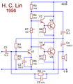 1956 H.C.Lin amplifier schematic - The Original Lin.png 1,115 × 1,279; 124 KB
-
 1972 modified Lin amplifier schematic.png 2,017 × 1,655; 124 KB
-
 2A3 class AB1 auto bias settings.png 1,685 × 1,062; 104 KB
-
 2A3 class AB1 fixed bias settings.png 1,675 × 949; 120 KB
-
 2A3 schematic Thordarson 1937.png 2,247 × 892; 98 KB
-
 78xx block diagram.png 1,322 × 690; 47 KB
-
 8-transistor zero-offset diamond buffer core.png 777 × 1,029; 65 KB
-
 Acrosound ST20 dual Loftin-White PP schematic.png 1,015 × 875; 63 KB
-
 Amplified zener.png 1,100 × 550; 9 KB
-
 AntiRIAA filter (Lipshitz and Jung 1980) RUS.png 1,329 × 503; 29 KB
-
 Arduino-based wow-and-flutter meter DSP arrangement.png 2,205 × 2,493; 122 KB
-
 As-built diamond-core audio power amp (v3) complete with PSU.png 5,901 × 2,589; 468 KB
-
 As-built diamond-core audio power amp.png 2,222 × 1,133; 319 KB
-
 Asymmetric double long-tailed pair.png 1,315 × 1,118; 51 KB
-
 Audio generator (Arduino Mini clone, R-2R matrix).png 1,963 × 930; 175 KB
-
 Audio spectrum analyzer - one filter-rectifier channel.png 1,271 × 896; 185 KB
-
 Basic bipolar long-tailed pair - common and diff currents.png 1,540 × 1,394; 61 KB
-
 Basic bipolar long-tailed pair - common and diff signals.png 2,449 × 1,757; 103 KB
-
 Basic bipolar long-tailed pair - current and voltage designations.png 1,230 × 1,454; 43 KB
-
 Basic bipolar long-tailed pair - introducing local feedback.png 1,252 × 1,506; 36 KB
-
 Basic MOS long-tailed pair - current and voltage designations.png 1,222 × 1,452; 52 KB
-
 Basic Vbe multiplier.png 717 × 690; 31 KB
-
 Battery-powered preamp - power management (UVLO, muting delay).png 2,118 × 948; 231 KB
-
 Baxendall tone control - Tandberg 1984.png 1,243 × 697; 82 KB
-
 Blackmer cell explanation.png 1,885 × 735; 95 KB
-
 Blackmer cell with grounded control pins.png 840 × 869; 70 KB
-
 Blackmer cell with nonzero control voltage.png 791 × 714; 58 KB
-
 Blackmer RMS detector evolution ENG.png 1,865 × 1,671; 258 KB
-
 Blackmer VCA cell basic with biasing.png 1,685 × 807; 93 KB
-
 Blackmer VCA cell basic.png 1,717 × 928; 95 KB
-
 Blackmer VCA cell improvements ENG.png 1,309 × 863; 103 KB
-
 Blackmer VCA cell improvements RUS.png 1,319 × 823; 91 KB
-
 Blackmer-Valley VCA cell basic.png 1,124 × 866; 61 KB
-
 Bootstrapped diamond follower.png 1,500 × 1,500; 96 KB
-
 Bootstrapping emitter follower to increase input impedance.png 990 × 1,001; 36 KB
-
 Bootstrapping emitter follower to suppress Early effect.png 1,824 × 1,103; 90 KB
-
 Brokaw cell 1974 original.PNG 792 × 545; 27 KB
-
 Cathode follower basic 680px.png 680 × 580; 8 KB
-
 Cathode follower concertina 1000px.png 1,000 × 932; 20 KB
-
 Cathode follower constant current 1000px.png 1,003 × 800; 17 KB
-
 CCI+ current conveyor bipolar BI.png 512 × 512; 5 KB
-
 CCI+ current conveyor unipolar BI.png 744 × 744; 23 KB
-
 CCI+ current conveyor unipolar MOS.png 744 × 744; 6 KB
-
 Clip clamp circuit for high-level signals (after Bob Cordell 2011).png 1,616 × 1,050; 153 KB
-
 Clip clamp circuit for line-level signals (Bob Cordell 2011).png 1,114 × 1,123; 142 KB
-
 Common-collector medium frequency model.png 2,321 × 755; 66 KB
-
 Common-source loadline setup.png 1,000 × 831; 20 KB
-
 Complementary long-tailed pair (CB second stage).png 1,257 × 1,709; 73 KB
-
 Complementary long-tailed pair (CE and CB second stage).png 2,486 × 1,712; 116 KB
-
 Complementary long-tailed pair (CE second stage).png 1,257 × 1,709; 65 KB
-
 Current conveyor symbol.png 400 × 400; 3 KB
-
 Current feedback op amp AD846 simplified.png 940 × 560; 18 KB
-
 Current feedback op amp capacitances.png 1,084 × 639; 23 KB
-
 Current feedback op amp differential line receiver single.png 1,040 × 652; 27 KB
-
 Current feedback op amp differential line receiver.png 1,040 × 652; 15 KB
-
 Current feedback op amp Franco2002.png 765 × 639; 15 KB
-
 Current feedback op amp ideal noniverting.png 1,440 × 716; 18 KB
-
 Current feedback op amp ideal structure.png 1,440 × 480; 14 KB
-
 Current feedback op amp notch filter.png 1,099 × 702; 34 KB
-
 Current feedback op amp simple triangle conveyor.png 800 × 690; 11 KB
-
 Current feedback op amp simple triangle.png 800 × 690; 13 KB
-
 Current feedback op amp single-input HDSL2 driver.png 1,318 × 730; 33 KB
-
 Current-adding subbandgap.png 962 × 483; 25 KB
-
 Dartzeel diamond-follower output stage.png 1,855 × 1,773; 239 KB
-
 Diode-string bandgap.PNG 1,100 × 600; 11 KB
-
 DRAM bus read voltage reference.png 1,282 × 822; 39 KB
-
 Economy muting relay coil drive for 30V-powered (opamp-based) devices.png 1,268 × 1,086; 122 KB
-
 Economy relay coil drive for battery-powered devices (simplest - series RC).png 1,415 × 1,129; 112 KB
-
 Economy relay coil drive for battery-powered devices.png 2,258 × 879; 86 KB
-
 EL84 reference UL configuration.png 1,629 × 1,043; 98 KB
-
 Emitter follower cutoff exampls.png 1,767 × 1,201; 98 KB
-
 Input impedance multiplication in an EF.png 1,783 × 471; 27 KB
-
 K293КП3А включение для снятия осциллограмм.png 946 × 494; 31 KB
-
 Lin amplifier evolution. 1. The original.png 1,054 × 990; 44 KB
-
 Lin amplifier evolution. 2. Transistor temperature sensing.png 1,059 × 992; 53 KB
-
 Lin amplifier evolution. 3. VAS loaded with CCS.png 1,056 × 995; 59 KB
-
 Lin amplifier evolution. 4. Dual supplies.png 1,058 × 938; 61 KB
-
 Lin amplifier evolution. 5. LTP front end.png 1,396 × 935; 77 KB
-
 Lin amplifier evolution. 6. Complementary output.png 1,350 × 996; 72 KB
-
 LM3915 independent control of LED current and voltage scale 02.png 1,182 × 1,289; 118 KB
-
 LM3915 stock control of LED current and voltage scale 02.png 1,223 × 1,362; 149 KB
-
 LM3915 two chips for 1.5dB step 20-led bargraph.png 2,147 × 1,169; 136 KB
-
 LM3915 блоксхема.png 864 × 996; 48 KB
-
 Log-antilog conversion - Blackmer cell.png 2,959 × 1,275; 158 KB
-
 Log-antilog conversion - unipolar mirror.png 2,968 × 780; 108 KB
-
 Long-tailed pair connection 1. Balanced in - Balanced out.png 1,040 × 1,040; 26 KB
-
 Long-tailed pair connection 2. Balanced in - Single out.png 1,040 × 1,040; 30 KB
-
 Long-tailed pair connection 3. Single in - balanced out.png 1,040 × 1,040; 31 KB
-
 Long-tailed pair connection 4. Single in - Single noninverting.png 1,040 × 1,040; 30 KB
-
 Long-tailed pair connection 5. Single in - Single inverting.png 1,040 × 1,040; 31 KB
-
 Long-tailed pair structure.png 1,519 × 1,128; 48 KB
-
 Low and high tempco Vbe multipliers.png 1,140 × 1,020; 62 KB
-
 Low impedance Vbe multiplier with LNFB.png 814 × 833; 40 KB
-
 Low impedance Vbe multiplier.png 741 × 811; 42 KB
-
 LTP+EF unity gain buffer basic.png 1,076 × 1,317; 61 KB
-
 LTP+EF unity gain buffer practical.png 1,076 × 1,317; 59 KB
-
 LTP+folded cascode for unipolar operation.png 1,945 × 982; 61 KB
-
 LTP+mirror family tree development.png 3,178 × 1,696; 111 KB
-
 Main channel of Dolby B-C NR.png 1,936 × 870; 162 KB
-
 Miller integrator topology (tube, transistor, opamp).png 2,443 × 818; 68 KB
-
 Mixed translinear cell I.png 480 × 480; 8 KB
-
 Mixed translinear cell II.png 480 × 480; 7 KB
-
 Mullard 3-3 rus.png 970 × 640; 35 KB
-
 Multiplied HV zener shunt sidebyside.png 1,044 × 351; 30 KB
-
 Multiplied HV zener shunt.png 525 × 690; 33 KB
-
 Output impedance division in an EF.png 1,783 × 478; 26 KB
-
 Phono stage topologies A1 active,series feedback.png 1,804 × 461; 60 KB
-
 Phono stage topologies A2 active,shunt feedback.png 1,802 × 444; 31 KB
-
 Phono stage topologies P1 passive,lumped.png 1,804 × 491; 37 KB
-
 Phono stage topologies P2 passive,split.png 1,805 × 487; 55 KB
-
 Phono stage topologies.png 1,806 × 1,982; 146 KB
-
 PP bridge 1 DEPP.png 1,000 × 680; 13 KB
-
 PP bridge 2 SEPP quasicomplementary.png 1,000 × 680; 11 KB
-
 PP bridge 3 SEPP complementary.png 1,000 × 680; 11 KB
-
 PP stage complementary CFP bi-fet.png 498 × 547; 17 KB
-
 PP stage complementary CFP.png 421 × 443; 13 KB
-
 PP stage complementary diamond follower 0 evolution.png 2,565 × 1,163; 145 KB
-
 PP stage complementary diamond follower 2 Hybrid.png 1,400 × 1,400; 99 KB
-
 PP stage complementary diamond follower 2.png 555 × 574; 21 KB
-
 PP stage complementary diamond follower 3.png 600 × 597; 15 KB
-
 PP stage complementary diamond follower 5 inbetween transistors.png 1,440 × 1,440; 113 KB
-
 PP stage complementary diamond follower 6 cfp output.png 1,400 × 1,400; 116 KB
-
 PP stage complementary diamond follower 7 adaptive CCS.png 1,277 × 1,326; 283 KB
-
 PP stage complementary diamond follower cap.png 1,260 × 900; 16 KB
-
 PP stage complementary diamond follower diode.png 1,400 × 1,400; 89 KB
-
 PP stage complementary diamond follower evolution 1.png 747 × 689; 15 KB
-
 PP stage complementary diamond follower evolution 2.png 924 × 771; 22 KB
-
 PP stage complementary diamond follower evolution 3.png 1,117 × 835; 41 KB
-
 PP stage complementary diamond follower link.png 1,260 × 900; 16 KB
-
 PP stage complementary diamond follower RCR.png 680 × 600; 9 KB
-
 PP stage complementary diamond follower.png 1,086 × 572; 31 KB
-
 PP stage complementary emitter follower 1.png 474 × 447; 14 KB
-
 PP stage complementary emitter follower 23.png 602 × 659; 25 KB
-
 PP stage complementary emitter follower type I.png 508 × 454; 15 KB
-
 PP stage complementary emitter follower type II.png 506 × 456; 15 KB
-
 PP stage complementary emitter follower type III.png 526 × 456; 16 KB
-
 PP stage complementary emitter follower.png 1,118 × 635; 39 KB
-
 PP stage complementary source follower.png 398 × 383; 11 KB
-
 PP stage OTL circlotron.png 654 × 463; 15 KB
-
 PP stage quasicomplementary asymmetry.png 978 × 794; 68 KB
-
 PP stage quasicomplementary Baxendall.png 503 × 655; 21 KB
-
 PP stage quasicomplementary Lin.png 509 × 589; 19 KB
-
 PP stage quasicomplementary source follower.png 489 × 479; 15 KB
-
 PP stage transformer-coupled bipolar.png 636 × 331; 14 KB
-
 PP stage transformer-coupled tube.png 638 × 338; 14 KB
-
 PP stage transformer-coupled.png 644 × 676; 25 KB
-
 PP stage Vbe multiplier.png 753 × 788; 52 KB
-

-
 Reduced tempco Vbe multipliers.png 1,168 × 1,132; 95 KB
-
 Regulated 6.3V heater DC from two Li-ion cells.png 1,653 × 1,131; 169 KB
-
 Replacement of 4053 switch with optorelays.png 2,985 × 1,203; 123 KB
-
 Replacement of 4066 switch with optorelays layout.png 644 × 737; 82 KB
-
 Replacement of 4066 switch with optorelays.png 4,748 × 2,064; 249 KB
-
 Revox B215 - implanting signal relays 06 - changes to accomodate ULN2003.png 1,218 × 1,145; 185 KB
-
 RIAA active filter topologies per Stanley Lipchitz.png 2,443 × 586; 78 KB
-
 RIAA active+passive opamp phono stage.png 1,939 × 688; 95 KB
-
 RIAA balanced split-filter passive phono stage.png 2,128 × 793; 135 KB
-
 RIAA basic opamp phono stage.png 1,916 × 731; 89 KB
-
 RIAA complete opamp phono stage.png 1,787 × 809; 73 KB
-
 RIAA filter topologies per Stanley Lipchitz.png 1,200 × 673; 66 KB
-
 RIAA lumped-filter passive phono stage.png 1,662 × 781; 62 KB
-
 RIAA split-filter passive phono stage.png 1,989 × 692; 68 KB
-
 Series zener examples.png 1,400 × 700; 55 KB
-
 Simple RC heat distribution model of a transistor on heatsink.png 1,901 × 1,869; 105 KB
-
 Step-by-step White follower synthesis.png 1,345 × 1,064; 95 KB
-
 Stereo level meter 2xLM3915, precision peak detectors.png 1,555 × 1,239; 260 KB
-
 Stop-at-platform relay for railway models.png 2,096 × 1,077; 186 KB
-
 Supressing inductive loops in an emitter follower 1.png 836 × 999; 31 KB
-
 Supressing inductive loops in an emitter follower 2.png 958 × 966; 27 KB
-
 Supressing inductive loops in an emitter follower.png 1,009 × 952; 30 KB
-
 TC zener supply and buffer.png 951 × 770; 32 KB
-
 Tektronix M377 instrumentation amp simplified.png 1,975 × 1,177; 68 KB
-
 The original LH0002 buffer schematic.png 1,400 × 1,400; 107 KB
-
 The original Loftin White amplifier.png 1,371 × 1,527; 134 KB
-
 The original Williamson amplifier schematic (1947).png 1,454 × 842; 180 KB
-
 The revised Williamson amplifier schematic (1949).png 1,445 × 837; 176 KB
-
 TI 502 schematic.png 1,007 × 657; 24 KB
-
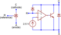 TL 431 symbol and basic structure ENG.png 1,463 × 837; 63 KB
-
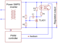 TL431 and opto SMPS control loop ENG.png 944 × 701; 48 KB
-
 TL431 basic comparator mode options ENG.png 2,455 × 750; 83 KB
-
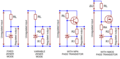 TL431 basic linear regulator options ENG.png 2,476 × 1,208; 128 KB
-
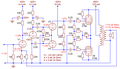
 TL431 schematic ENG.png 2,266 × 1,725; 158 KB
-
 Triple-twin SE amplifier 2B6 tube.png 947 × 948; 42 KB
-
 Triple-twin SE amplifier 6N6G tube.png 838 × 854; 35 KB
-
 Undervoltage battery switch, TL431+PMOS.png 1,591 × 692; 66 KB
-
 UPC1237 speaker protection 1. Basic as in datasheet.png 1,436 × 946; 163 KB
-
 UPC1237 speaker protection 2. Decrease relay current with RC.png 1,553 × 801; 169 KB
-
 UPC1237 speaker protection 3. Add delayed muting relay.png 1,815 × 828; 218 KB
-
 UPC1237 speaker protection 4. Add simple overload detector.png 1,468 × 751; 107 KB
-

-
 Vbe multiplier with increased tempco.png 1,398 × 1,252; 77 KB
-
 VPTAT temp chart RUS.png 1,100 × 640; 87 KB
-
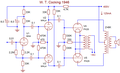 W.T.Cocking Quality Amplifier, 1946 12-Watt version.png 1,339 × 815; 119 KB
-
 Western Electric 86 300B output stage.png 847 × 742; 49 KB
-
 Western Electric 91 300B output stage.png 607 × 722; 49 KB
-
 Western Electric 92 300B output stage.png 956 × 943; 69 KB
-
 Widlar 1964 prototype 800x800px color.png 800 × 800; 16 KB
-
 Widlar 1964 prototype 800x800px.PNG 800 × 800; 16 KB
-
 Widlar 1964 uA702 800x800px color.png 800 × 800; 19 KB


_complete_with_PSU.png)


.png)


.png)


.png)
.png)

.png)
.png)
.png)


_devices.png)
.png)


.png)


.png)
.png)


_RUS.png)
.png)