Category:Bipolar circuits
Jump to navigation
Jump to search
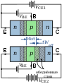
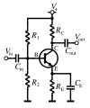
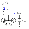
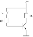
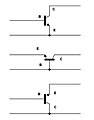
English: Bipolar junction transistor circuit diagrams.
Subcategories
This category has the following 4 subcategories, out of 4 total.
B
- Bipolar mixer circuits (9 F)
- BJT biasing circuits (33 F)
I
Media in category "Bipolar circuits"
The following 64 files are in this category, out of 64 total.
-
 AD1315.svg 549 × 549; 54 KB
-
 AMM MG-Einfluss U.svg 350 × 250; 83 KB
-
 Basic BJT Current Mirror.svg 125 × 150; 12 KB
-
 Bipolar current follower hybrid pi.PNG 672 × 550; 40 KB
-
 Bipolar current follower.png 894 × 1,013; 45 KB
-
 Bipolar current follower.PNG 642 × 658; 41 KB
-
 Bipolar current follower2.PNG 753 × 770; 61 KB
-
 Bipolar transresistance amplifier.PNG 534 × 529; 31 KB
-
 Bipolar voltage amplifier.PNG 611 × 742; 55 KB
-
 Bipolar Voltage Follower.png 483 × 454; 21 KB
-
 Bipolaris tranzisztor.PNG 300 × 135; 2 KB
-
 Bipolartransistor (elektrische Spannungen).svg 275 × 200; 18 KB
-
 BJT amplifer with pypass capacitors.svg 350 × 320; 76 KB
-
 BJT amplifier with parasitic capacitors.svg 440 × 320; 109 KB
-
 BJT Switch.jpg 1,055 × 665; 24 KB
-
 BJT transistor in use on switching.png 130 × 220; 874 bytes
-
 Common base.png 325 × 286; 5 KB
-
 Common Collector Principle.png 1,484 × 960; 27 KB
-
 Common collector.png 282 × 295; 4 KB
-
 Common Emitter Principle.png 1,484 × 846; 25 KB
-
 Current mirror.png 671 × 366; 30 KB
-
 Early effect (NPN) zh hans.svg 250 × 340; 58 KB
-
 Early effect (NPN) zh hant.svg 250 × 340; 58 KB
-
 Early effect (NPN)-ru.svg 742 × 1,006; 64 KB
-
 Early effect (NPN).svg 250 × 340; 58 KB
-
 Ecretage par transistor.gif 385 × 257; 3 KB
-
 Földelt emitteres mérőkapcsolás.jpg 596 × 227; 9 KB
-
 Ibe-ube.jpg 152 × 121; 5 KB
-
 Ic-uce.jpg 134 × 114; 5 KB
-
 Impedanzwandler (Einstufig, Kollektorschaltung).svg 177 × 213; 15 KB
-
 Impedanzwandler (Zweistufig, Kollektorschaltung).svg 220 × 198; 19 KB
-
 Impedanzwandler (Zweistufig, Kollektorschaltung, ea).svg 206 × 269; 19 KB
-
 Impedanzwandler (Zweistufig, Kollektorschaltung, komplementär).svg 230 × 354; 23 KB
-
 Montage avec transistor.png 998 × 613; 17 KB
-
 Montage diode zéner et transistor 2.png 1,201 × 674; 24 KB
-
 Montage diode zéner et transistor.png 1,071 × 708; 19 KB
-
 Multiple BJT Current Mirror.svg 225 × 150; 19 KB
-
 NPN BJT - Structure & circuit.svg 250 × 300; 19 KB
-
 NPN BJT Class A Transformer-Coupled Amplifier circuit.svg 350 × 300; 70 KB
-
 NPN BJT switch application circuit.svg 310 × 220; 55 KB
-
 NPN common emitter AC.svg 176 × 210; 4 KB
-
 NPN phase splitter.svg 190 × 350; 108 KB
-
 PNP BJT - Structure & circuit.svg 250 × 300; 21 KB
-
 PNP phase splitter.svg 684 × 1,059; 1 KB
-
 Retegtranzisztor.PNG 320 × 200; 3 KB
-
 Schottky-Transistor-ersatz.svg 200 × 200; 14 KB
-
 Simple bipolar mirror.PNG 500 × 500; 3 KB
-
 Simple bipolar mirror.svg 510 × 510; 21 KB
-
 TRA1D.JPG 340 × 162; 8 KB
-
 TransCommut.png 191 × 214; 1 KB
-
 Transconductunce-Verstärker als Schalter.svg 443 × 443; 41 KB
-
 Transistor amplifier design.svg 997 × 157; 96 KB
-
 Transistor grounded-emitter configuration.svg 185 × 160; 17 KB
-
 Transistor Simple Circuit Diagram with NPN Labels.svg 720 × 720; 7 KB
-
 Transistore BJT in uso come amplificatore.png 395 × 152; 2 KB
-
 Transistorgrundschaltungen.svg 800 × 420; 86 KB
-
 Tranzisztor alapkapcsolásai.jpg 575 × 734; 18 KB
-
 Tranzisztor négynegyedes karakterisztikája.jpg 347 × 238; 12 KB
-
 Wilson Current Mirror (Currents Labelled).svg 125 × 200; 32 KB
-
 Wilson Current Mirror Output Resistance.svg 225 × 250; 49 KB
-
 Wilson Current Mirror.svg 125 × 200; 16 KB
-
 Áramerősítési karakterisztika.jpg 171 × 123; 5 KB
-
 Émetteur commun.svg 378 × 242; 31 KB
-
 Схема замещения 1.png 301 × 158; 1 KB


_zh_hans.svg)
_zh_hant.svg)
-ru.svg)
.svg)


.svg)
.svg)
.svg)
.svg)


.svg)


.svg)