File:3 phase rectification 2.png
Jump to navigation
Jump to search
Size of this preview: 377 × 599 pixels. Other resolutions: 151 × 240 pixels | 302 × 480 pixels | 850 × 1,350 pixels.
Original file (850 × 1,350 pixels, file size: 24 KB, MIME type: image/png)
Captions
Captions
Add a one-line explanation of what this file represents
Summary
[edit]| Description |
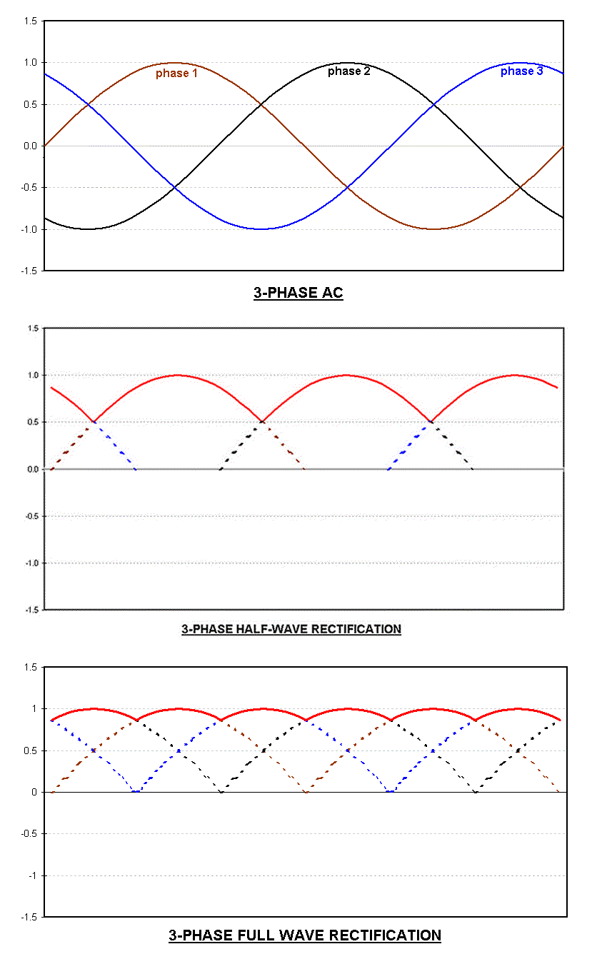
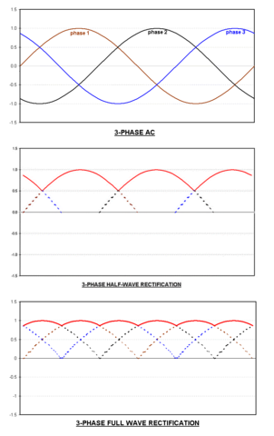
English: Waveforms for a typical 3-phase half-wave and full-wave rectifiers. The top plot shows the individual three phase signals, the middle plot shows the half-wave rectifier output in solid curve and the bottom plot shows the full-wave rectifier output in solid curve. The 'T' in time is the time period of individual signals and \scriptstyle V_\mathrm{peak} is the amplitude of each of the three input signals. |
| Date | 28 February 2009 (original upload date) |
| Source | original digital image. Own work. |
| Author | Suckindiesel (talk) (Uploads) |
| Other versions |
[]
.png:
.jpg:
|


|
File:3 phase rectification 2.svg is a vector version of this file. It should be used in place of this PNG file when not inferior.
File:3 phase rectification 2.png → File:3 phase rectification 2.svg
For more information, see Help:SVG. |
 |
Licensing
[edit]
This file is licensed under the Creative Commons Attribution 3.0 Unported license.
- You are free:
- to share – to copy, distribute and transmit the work
- to remix – to adapt the work
- Under the following conditions:
- attribution – You must give appropriate credit, provide a link to the license, and indicate if changes were made. You may do so in any reasonable manner, but not in any way that suggests the licensor endorses you or your use.
Original upload log
[edit]
Transferred from en.wikipedia to Commons by Sfan00_IMG using CommonsHelper.
The original description page was here. All following user names refer to en.wikipedia.
- 2009-02-28 23:23 Suckindiesel 850×1350× (25021 bytes) original digital image
File history
Click on a date/time to view the file as it appeared at that time.
| Date/Time | Thumbnail | Dimensions | User | Comment | |
|---|---|---|---|---|---|
| current | 15:07, 23 July 2013 | | 850 × 1,350 (24 KB) | File Upload Bot (Magnus Manske) (talk | contribs) | Transfered from en.wikipedia by User:Sfan00_IMG using CommonsHelper |
You cannot overwrite this file.
File usage on Commons
The following 9 pages use this file:
- File:3 phase rectification 2-ru.svg
- File:3 phase rectification 2.png
- File:3 phase rectification 2.svg
- File:DC voltage profile of B6 three-phase full-wave rectifier.jpg
- File:Terminales positivos y negativos del rectificador.png
- File:Waveform fullwave rectifier3.png
- File:Zwezda-Larionow.jpg
- File:Звезда-ларионов.jpg
- Template:Other versions/3 phase rectification