File:Triod-english-text.png
From Wikimedia Commons, the free media repository
Jump to navigation
Jump to search

Size of this preview: 443 × 599 pixels. Other resolutions: 177 × 240 pixels | 355 × 480 pixels | 646 × 874 pixels.
Original file (646 × 874 pixels, file size: 247 KB, MIME type: image/png)
File information
Structured data
Captions
Captions
Add a one-line explanation of what this file represents
Summary
[edit]| DescriptionTriod-english-text.png |
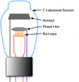
English: Cutaway drawing showing the construction of a low power triode vacuum tube. The triode, invented in 1906 by Lee De Forest, was the first device which could amplify and it was used widely in radios, televisions, audio systems and radio transmitters until it was largely replaced by the transistor in the 1960s.
It consists of an evacuated glass tube containing three concentric electrodes: a cathode heated by a filament, a grid, and a plate. The three outer electrodes are shown with part cut away to reveal the construction. The cathode is a narrow metal tube down the center, containing the filament, a loop of high resistance nichrome wire with a separate current passing through it to heat. It heats the cathode red hot (800-1000° C). The heat causes the cathode to release electrons into the vacuum inside the tube. The cathode is coated with alkaline earth oxides such as calcium oxide or thorium to reduce it's work function, to increase the electron production. The negative electrons are attracted to the positive voltage on the plate, a cylinder of sheet metal surrounding the cathode, and travel to it, creating an electric current from the cathode to the plate. The grid is a screen or helix of wires between cathode and plate. The electrons have to pass through the grid wires to get to the plate. A voltage applied between the grid and cathode can control the cathode-plate current. A negative voltage on the grid will repel some of the electrons, so fewer get through to the plate, reducing the plate current. A positive voltage on the grid will attract more electrons through, increasing the plate current. Thus a small voltage on the grid can control a much larger plate current, which can be used to amplify. Almost all the air is evacuated from the sealed glass envelope, to about 10-9 atm, so the electrons will not be obstructed by gas atoms. The parts inside the tube are supported by wires which connect the electrodes to pins on the bottom of the tube. A thin shiny spot of barium metal (not shown) is evaporated onto the glass during manufacture. This is called a getter and helps maintain the vacuum by absorbing residual gas released by the metal parts after evacuation. |
| Date | |
| Source | Own work |
| Author | Svjo |
| Other versions |
[edit] .svg:
.png:
.jpg:
|
Licensing
[edit]I, the copyright holder of this work, hereby publish it under the following license:
This file is licensed under the Creative Commons Attribution-Share Alike 3.0 Unported license.
- You are free:
- to share – to copy, distribute and transmit the work
- to remix – to adapt the work
- Under the following conditions:
- attribution – You must give appropriate credit, provide a link to the license, and indicate if changes were made. You may do so in any reasonable manner, but not in any way that suggests the licensor endorses you or your use.
- share alike – If you remix, transform, or build upon the material, you must distribute your contributions under the same or compatible license as the original.
File history
Click on a date/time to view the file as it appeared at that time.
| Date/Time | Thumbnail | Dimensions | User | Comment | |
|---|---|---|---|---|---|
| current | 10:00, 1 July 2013 |  | 646 × 874 (247 KB) | Svjo (talk | contribs) | User created page with UploadWizard |
You cannot overwrite this file.
File usage on Commons
The following 10 pages use this file:
Metadata
This file contains additional information such as Exif metadata which may have been added by the digital camera, scanner, or software program used to create or digitize it. If the file has been modified from its original state, some details such as the timestamp may not fully reflect those of the original file. The timestamp is only as accurate as the clock in the camera, and it may be completely wrong.
| Horizontal resolution | 35.43 dpc |
|---|---|
| Vertical resolution | 35.43 dpc |
| Software used |
Hidden categories:


