File:ECL.svg
Jump to navigation
Jump to search

Size of this PNG preview of this SVG file: 772 × 600 pixels. Other resolutions: 309 × 240 pixels | 618 × 480 pixels | 989 × 768 pixels | 1,280 × 994 pixels | 2,560 × 1,988 pixels | 851 × 661 pixels.
Original file (SVG file, nominally 851 × 661 pixels, file size: 56 KB)
Captions
Captions
Add a one-line explanation of what this file represents
Summary
[edit]
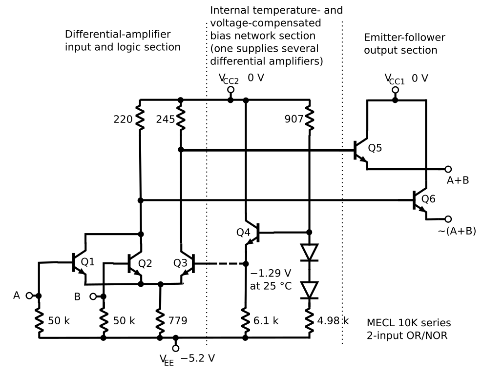
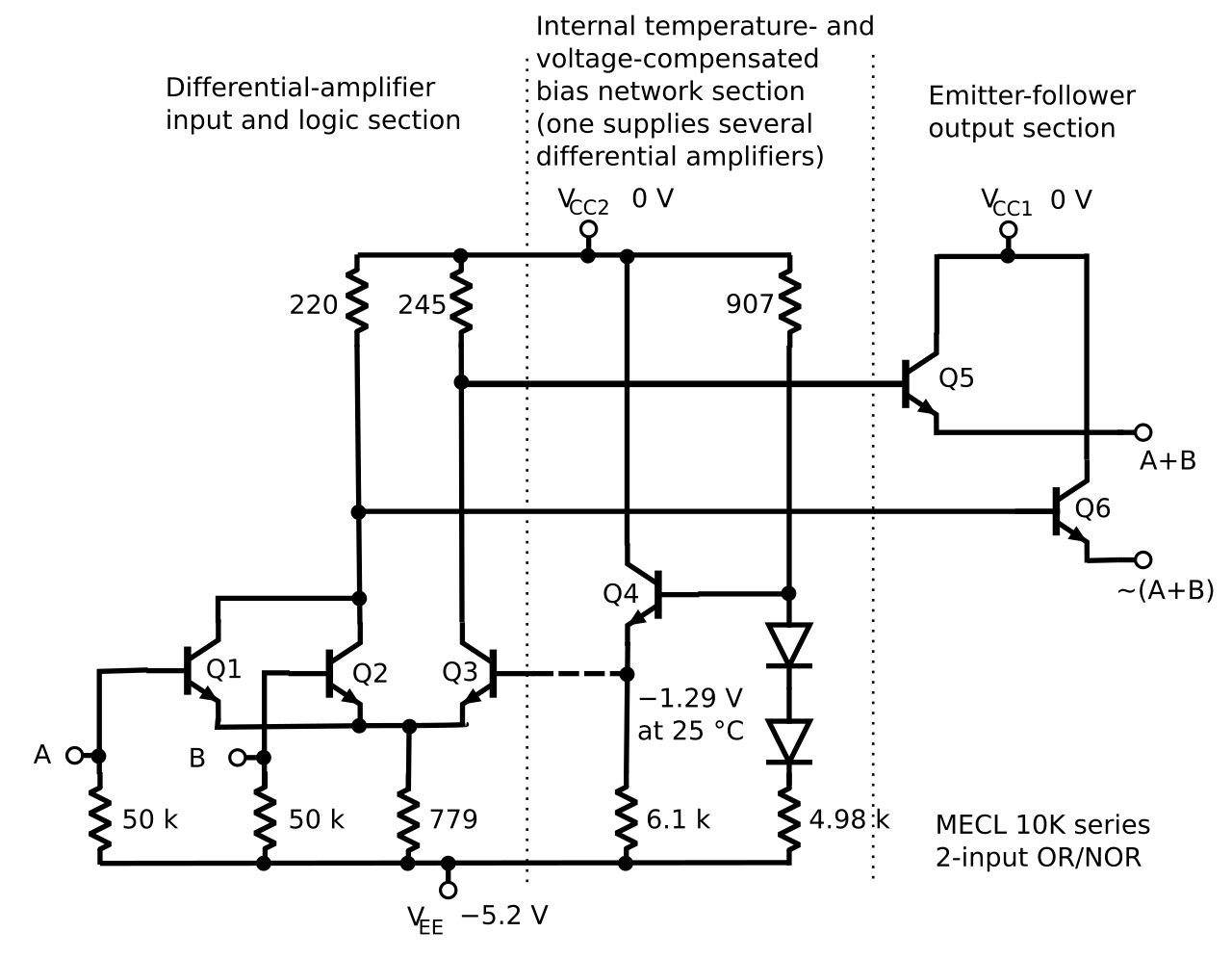
| Description | Motorola ECL 10,000 basic gate circuit diagram. Source: 1991 Motorola Military_MECL, (Chapter 1)p. "1-4" |
| Date | |
| Source | Own work |
| Author | Gerry Ashton |
Licensing
[edit]
I, the copyright holder of this work, hereby publish it under the following licenses:

|
Permission is granted to copy, distribute and/or modify this document under the terms of the GNU Free Documentation License, Version 1.2 or any later version published by the Free Software Foundation; with no Invariant Sections, no Front-Cover Texts, and no Back-Cover Texts. A copy of the license is included in the section entitled GNU Free Documentation License. |
This file is licensed under the Creative Commons Attribution-Share Alike 3.0 Unported, 2.5 Generic, 2.0 Generic and 1.0 Generic license.
- You are free:
- to share – to copy, distribute and transmit the work
- to remix – to adapt the work
- Under the following conditions:
- attribution – You must give appropriate credit, provide a link to the license, and indicate if changes were made. You may do so in any reasonable manner, but not in any way that suggests the licensor endorses you or your use.
- share alike – If you remix, transform, or build upon the material, you must distribute your contributions under the same or compatible license as the original.
You may select the license of your choice.
File history
Click on a date/time to view the file as it appeared at that time.
| Date/Time | Thumbnail | Dimensions | User | Comment | |
|---|---|---|---|---|---|
| current | 06:43, 27 September 2024 | | 851 × 661 (56 KB) | Jeffrey Kim (talk | contribs) | File uploaded using svgtranslate tool (https://svgtranslate.toolforge.org/). Added translation for yue. |
| 06:00, 12 February 2018 |  | 851 × 661 (55 KB) | Mikhail Ryazanov (talk | contribs) | punctuation; all connections; cleanup of Inkscape junk | |
| 20:57, 10 September 2015 |  | 851 × 661 (104 KB) | McNeight (talk | contribs) | Added wire junctions to clarify connections between components, updated metadata, and ran through Inkscape 0.91 "Clean up document". | |
| 04:44, 20 October 2009 |  | 851 × 661 (119 KB) | Dicklyon (talk | contribs) | Bigger text, tighter layout, smaller bounding box, so it will be easier to read; omit unneeded statement about how to read a schematic; edit labels a bit. | |
| 00:21, 30 August 2007 |  | 990 × 765 (79 KB) | Gerry Ashton (talk | contribs) | Cosmetic improvement of position of resistor values. | |
| 01:33, 29 August 2007 |  | 990 × 765 (79 KB) | Gerry Ashton (talk | contribs) | Include Q3 in differential amplifier section instead of bias network. | |
| 16:54, 28 August 2007 |  | 990 × 765 (79 KB) | Gerry Ashton (talk | contribs) | Label the 907 ohm resistor. | |
| 16:46, 28 August 2007 |  | 990 × 765 (78 KB) | Gerry Ashton (talk | contribs) | Fix an error; a connection from base of Q5 should have extended all the way to the collector of Q3. | |
| 22:00, 26 August 2007 |  | 990 × 765 (78 KB) | Gerry Ashton (talk | contribs) | Motorola ECL 10,000 basic gate circuit diagram. Based on William Blood, 1972, _MECL System Design Handbook_, 2d ed., Motorola Semiconductor Products Inc., p. 1. | |
| 21:20, 26 August 2007 |  | 990 × 765 (80 KB) | Gerry Ashton (talk | contribs) | {{Information |Description=Motorola ECL 10,000 basic gate circuit diagram |Source=self-made |Date=2007-08-26 |Author= Gerry Ashton }} |
You cannot overwrite this file.
File usage on Commons
There are no pages that use this file.
File usage on other wikis
The following other wikis use this file:
- Usage on ar.wikipedia.org
- Usage on ca.wikipedia.org
- Usage on en.wikipedia.org
- Usage on en.wikibooks.org
- Usage on es.wikipedia.org
- Usage on fa.wikipedia.org
- Usage on fr.wikipedia.org
- Usage on hu.wikipedia.org
- Usage on id.wikipedia.org
- Usage on it.wikipedia.org
- Usage on ja.wikipedia.org
- Usage on ko.wikipedia.org
- Usage on sr.wikipedia.org