File:Crystal radio with impedance matching.svg
Jump to navigation
Jump to search

Size of this PNG preview of this SVG file: 677 × 426 pixels. Other resolutions: 320 × 201 pixels | 640 × 403 pixels | 1,024 × 644 pixels | 1,280 × 805 pixels | 2,560 × 1,611 pixels.
Original file (SVG file, nominally 677 × 426 pixels, file size: 32 KB)
Captions
Captions
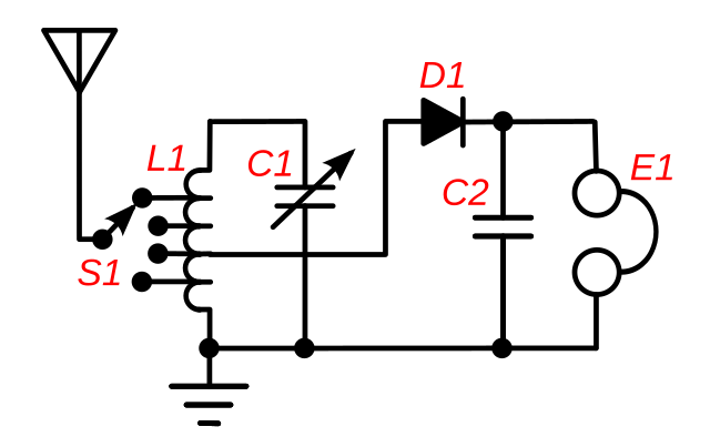
Circuit of a crystal radio
Summary
[edit]
| Description |
English: A crystal radio receiver circuit that uses impedance matching to increase the power transferred from the antenna through the receiver to the earphone E1. This type of circuit was used in higher quality radios around 1920. Maximum power is transferred from one circuit to another when their impedance (resistance) is equal. However, in a crystal receiver, the impedance of the antenna-ground circuit (around 10-200 ohms) is far less than the impedance of the tuned circuit (L1, C1) (thousands of ohms at resonance) and varies depending on the length of the antenna, etc.. Therefore the antenna is connected to a tap across only a portion of the coil's turns, using a multiposition switch, S1. This makes the tuning coil L1 act as an impedance matching autotransformer in addition to its tuning function, transforming the high impedance of the tuned circuit down by the square root of the turns ratio to match the antenna. The switch S1 is adjusted until the radio station is loudest in the earphone. The impedance of the crystal detector D1 is also matched to the tuned circuit by connecting the detector, like the antenna, to a tap on the coil. In addition to improving power transfer, impedance matching also improves selectivity of the receiver (its ability to reject interfering signals at nearby frequencies) by reducing the resistive "loading" of the tuned circuit, increasing the Q factor. |
| Date | |
| Source | Own work |
| Author | Chetvorno |
| SVG development | This diagram was created with Inkscape, or with something else. This diagram uses translateable embedded text. |
Licensing
[edit]
I, Chetvorno, the author of this drawing, release it into the public domain for any use whatever
| I, the copyright holder of this work, release this work into the public domain. This applies worldwide. In some countries this may not be legally possible; if so: I grant anyone the right to use this work for any purpose, without any conditions, unless such conditions are required by law. |
File history
Click on a date/time to view the file as it appeared at that time.
| Date/Time | Thumbnail | Dimensions | User | Comment | |
|---|---|---|---|---|---|
| current | 04:05, 9 May 2017 | | 677 × 426 (32 KB) | Chetvorno (talk | contribs) | Replaced invalid Inkscape SVG version with "plain SVG" version that passes validation |
| 02:32, 28 January 2016 |  | 677 × 426 (40 KB) | Chetvorno (talk | contribs) | Increased line widths and tweaked location of components | |
| 02:24, 28 January 2016 |  | 677 × 426 (40 KB) | Chetvorno (talk | contribs) | Increased line width and tweaked location of components | |
| 09:40, 20 May 2010 |  | 677 × 426 (38 KB) | Chetvorno (talk | contribs) | {{Information |Description={{en|A crystal radio receiver circuit that uses Wikipedia:impedance matching to increase the power transferred from the antenna to the earphone. The maximum power is transferred from one circuit to another when their imped |
You cannot overwrite this file.
File usage on Commons
There are no pages that use this file.
File usage on other wikis
The following other wikis use this file:
- Usage on de.wikipedia.org
- Usage on en.wikipedia.org
- Usage on es.wikipedia.org