File:As-built diamond-core audio power amp.png
Jump to navigation
Jump to search
Size of this preview: 800 × 408 pixels. Other resolutions: 320 × 163 pixels | 640 × 326 pixels | 1,024 × 522 pixels | 1,280 × 653 pixels | 2,222 × 1,133 pixels.
Original file (2,222 × 1,133 pixels, file size: 319 KB, MIME type: image/png)
Captions
Captions
Add a one-line explanation of what this file represents
Summary
[edit]
| Description |
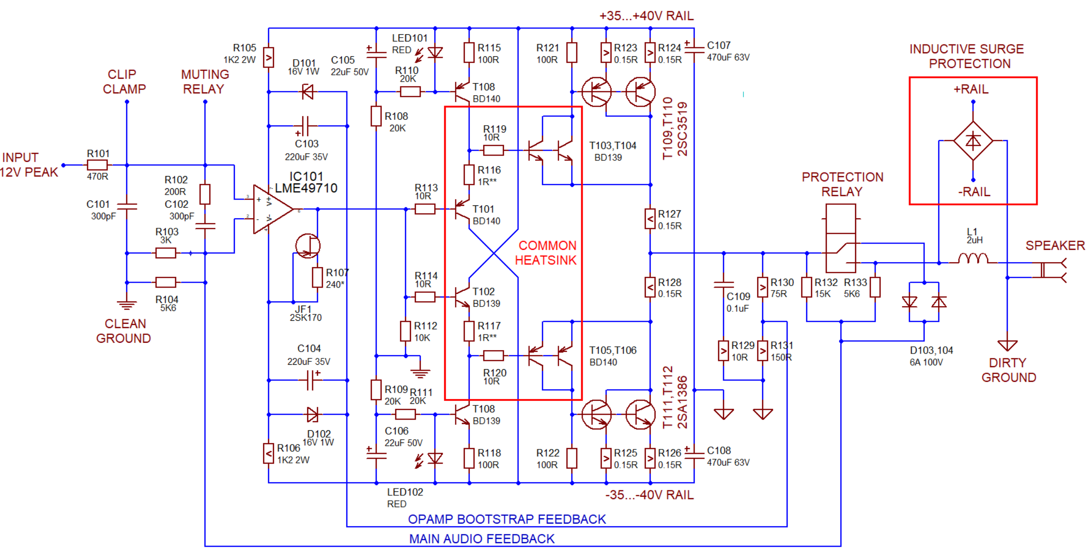
English: As-built audio power amp schematic built around a diamond-buffer core, with Sziklai-type current boosters. This is my take on a classic 1987 circuit by V.Ageev, with modern parts and added output protection components. Practical output power from +/-40V rails: 75 WRMS into 8 Ohm (if the rails are stiff enough). The bootstrapped opamp has a gain of 3, and thus requires a full +/-12 Vpk input signal (another opamp).
Русский: Ядро УМЗЧ мощностью 75 Вт/канал (на 8 Ом при источнике питания +/-40В), построенного по мотивам схемы Агеева из Радио 2/87. Показано собственно ядро УМЗЧ + защитный обвес на выходе. Коэффициент усиления: 3, т.е. требуется ещё один каскад усиления с размахом +/- 12в пик-пик. |
| Date | |
| Source | Own design based on 1987 work by V.Ageev, drawn in old Labcenter Isis |
| Author | user:Retired electrician |
| This work is ineligible for copyright and therefore in the public domain because it consists entirely of information that is common property and contains no original authorship. |
File history
Click on a date/time to view the file as it appeared at that time.
| Date/Time | Thumbnail | Dimensions | User | Comment | |
|---|---|---|---|---|---|
| current | 01:11, 20 November 2022 | | 2,222 × 1,133 (319 KB) | Retired electrician (talk | contribs) | minor fix |
| 00:32, 20 November 2022 |  | 2,222 × 1,133 (318 KB) | Retired electrician (talk | contribs) | {{Information |Description={{en|As-built audio power amp schematic built around a diamond-buffer core, with Sziklai-type current boosters. This is a modern rendition of a 1987 circuit by V.Ageev, with modern parts and added output protection components. Practical output power from +/-40V rails = 75WRMS into 8 Ohm. The bootstrapped opamp has a gain of 3, and thus requires a full +/-12 Vpk input signal (another opamp). }} {{ru|Ядро УМЗЧ мощностью 75 Вт/канал (на 8 Ом при источнике питания +/-40... |
You cannot overwrite this file.
File usage on Commons
There are no pages that use this file.